概述
本篇介绍如何利用pybullet仿真环境,对四足机器人单腿实现简单控制,实现机器人足端按照我们要求的轨迹,从一个随机点移动到另外一个随机点,具体效果如以下视频
pybullet仿真:随机落足点+足端轨迹规划
一、控制原理
1、随机落足点生成
一般来说,机器人控制中的位置信息由一个坐标点来决定,即[x y z]。我们可以利用python的随机函数生成指定范围内的数值,来模拟足端在现实世界当中将要到达的目标点。具体代码如下:
def get_radom_location(n):

    location = []
    for i in range(n):
        x = random.uniform(-0.1, 0.1)
        y = random.uniform(-0.1, 0.1) + abad_offset
        z = random.uniform(-0.02, 0.02) + body_height
        # z = -0.25
        location.append([x, y, z])
    print(location)
    return location
def get_radom_location(n): location = [] for i in range(n): x = random.uniform(-0.1, 0.1) y = random.uniform(-0.1, 0.1) + abad_offset z = random.uniform(-0.02, 0.02) + body_height # z = -0.25 location.append([x, y, z]) print(location) return location
复制
其中 abad_offset 和 body_height 是 四足机器人的机身结构参数,用于确定腿部相较于机身中心的偏移。函数输入 n 指的是需要生成多少组xyz坐标,输出为一个二维数组,其结构形式如下:
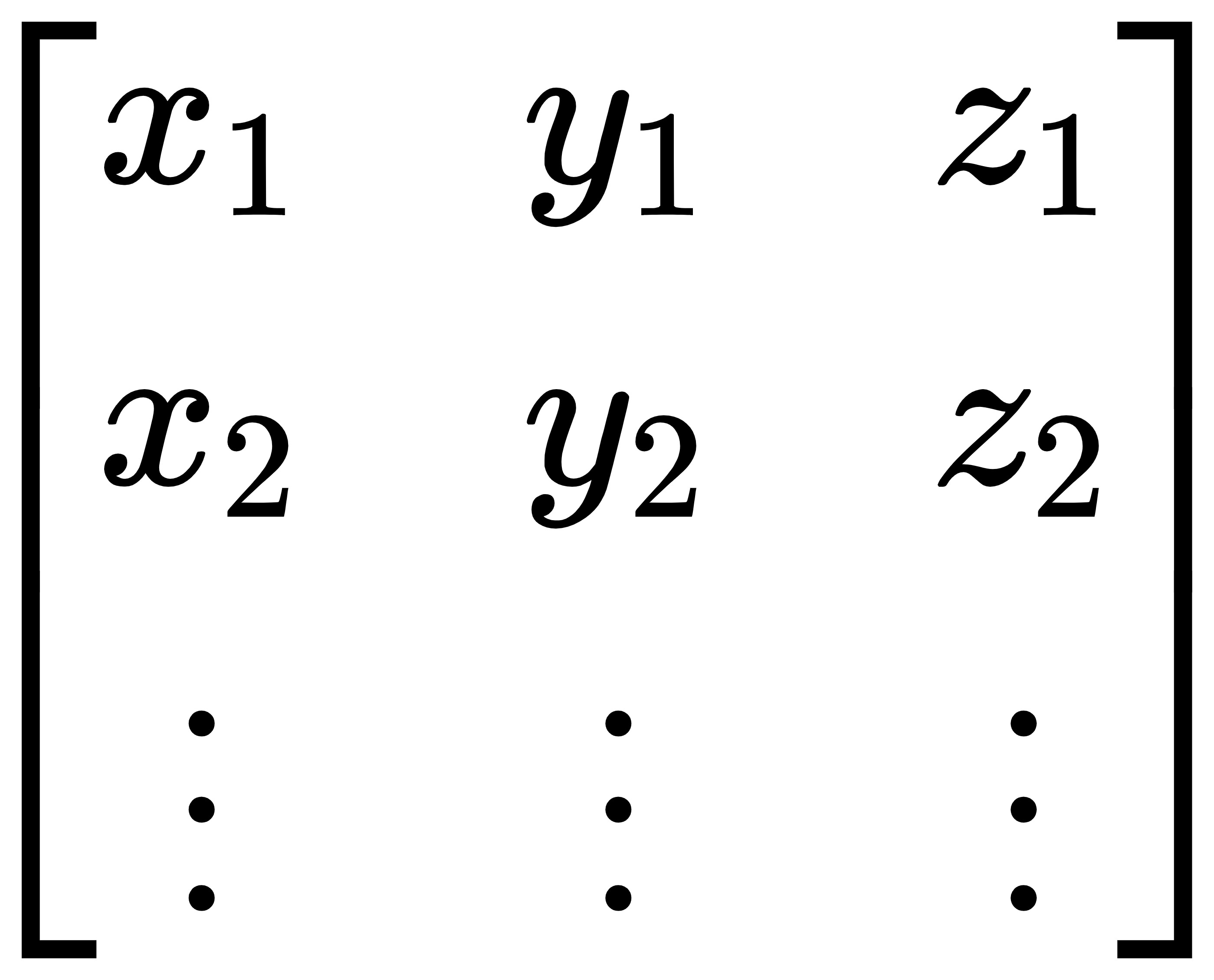
2、轨迹规划
该部分在之前的文章中已经详细介绍过了,对具体数学原理感兴趣的小伙伴可以去翻看以下往期文章:
足端轨迹规划-八次多项式轨迹
足端轨迹规划-复合摆线轨迹
足端轨迹规划-贝塞尔曲线
这里以八次多项式为例给出代码:
# 八次多项式
def polynomial_trajectory(phase, p0, pf):
    Sx, Sy, Sz = pf - p0
    x = (6 * Sx * phase ** 5) / (T ** 5) - (15 * Sx * phase ** 4) / (T ** 4) + (10 * Sx * phase ** 3) / (T ** 3)
    y = (6 * Sy * phase ** 5) / (T ** 5) - (15 * Sy * phase ** 4) / (T ** 4) + (10 * Sy * phase ** 3) / (T ** 3)
    z = 384 * (-2 * H + Sz) / T ** 8 * phase ** 8 + 24 * (128 * H - 59 * Sz) / T ** 7 * phase ** 7 + 4 * (
                -1216 * H + 503 * Sz) / T ** 6 * phase ** 6 \
        + 6 * (640 * H - 229 * Sz) / T ** 5 * phase ** 5 + 3 * (-512 * H + 151 * Sz) / T ** 4 * phase ** 4 + 2 * (
                    128 * H - 29 * Sz) / T ** 3 * phase ** 3

    return np.array([x, y, z]) + p0
# 八次多项式 def polynomial_trajectory(phase, p0, pf): Sx, Sy, Sz = pf - p0 x = (6 * Sx * phase ** 5) / (T ** 5) - (15 * Sx * phase ** 4) / (T ** 4) + (10 * Sx * phase ** 3) / (T ** 3) y = (6 * Sy * phase ** 5) / (T ** 5) - (15 * Sy * phase ** 4) / (T ** 4) + (10 * Sy * phase ** 3) / (T ** 3) z = 384 * (-2 * H + Sz) / T ** 8 * phase ** 8 + 24 * (128 * H - 59 * Sz) / T ** 7 * phase ** 7 + 4 * ( -1216 * H + 503 * Sz) / T ** 6 * phase ** 6 \ + 6 * (640 * H - 229 * Sz) / T ** 5 * phase ** 5 + 3 * (-512 * H + 151 * Sz) / T ** 4 * phase ** 4 + 2 * ( 128 * H - 29 * Sz) / T ** 3 * phase ** 3 return np.array([x, y, z]) + p0
复制
函数输入分别为相位,起点,终点,输出为当前相位的位置点。
3、逆运动学
有了具体的足端位置点还不够,我们还需要转化成各关节的角度才能实现我们对腿部的控制,因此这里就需要用到逆运动学。通过简单的几何分析,给出二维,三维状态下的逆运动学控制代码作为参考:
# 逆运动学(二维)
def inverse_kinematic(x, y):
    theta2 = -np.pi + np.arccos((L1**2 + L2**2-x**2-y**2)/(2*L1*L2))
    theta1 = np.arccos((x**2+y**2+L1**2-L2**2)/(2*np.sqrt(x**2+y**2)*L1))-np.arctan2(x, abs(y))
    return [0, theta1, theta2]


# 逆运动学(三维)
def inverse_kinematic2(x, y, z):
    z_ = np.sqrt(y ** 2 + z ** 2 - abad_offset ** 2)
    theta0 = np.arctan2(z_, abad_offset) - np.arctan2(-z, y)
    c2 = (-L1 ** 2 - L2 ** 2 + x ** 2 + z_ ** 2) / (2 * L1 * L2)
    if c2 > 1:
        c2 = 1
    s2 = np.sqrt(1 - c2 ** 2)
    theta2 = -np.arctan2(s2, c2)
    theta1 = - np.arctan2(-z_, x) + np.arctan2(L2 * s2, L1 + L2 * c2) - np.pi/2
    # print(theta0, theta1, theta2)
    return theta0, theta1, theta2
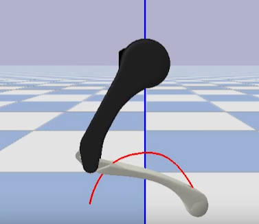
4、绘制足端轨迹
如果以前环节你都实现了,就已经可以通过代码来控制我们的四足机器人单腿了。接下来我们还可以来点锦上添花的,利用pybullet自带的api可以绘制出足端所走过的轨迹,方便我们后续观察和调整。
三、完整代码
以上就是重要核心环节的实现了,我们对代码稍加修饰,就可以在仿真环境中实现视频中看到的效果了,完整代码如下,大家可以自行尝试以下
import pybullet_data as pd
import pybullet as p
import numpy as np
import time
import random

motor_list = [0, 1, 2]
init_pos = [-0.05, 0, 0.6]
toe_id = 3

T = 0.2
S = 0.3
H = 0.1

abad_offset = -0.08505
L1 = 0.2
L2 = 0.2
body_height = -0.25


def get_radom_location(n):

    location = []
    for i in range(n):
        x = random.uniform(-0.1, 0.1)
        y = random.uniform(-0.1, 0.1) + abad_offset
        z = random.uniform(-0.02, 0.02) + body_height
        # z = -0.25
        location.append([x, y, z])
    print(location)
    return location


# 摆线轨迹
def fe(t):
    temp = t/T - np.sin((4*np.pi*t)/T)/(4*np.pi)
    return temp


def cycloid_trajectory(t, p0, pf):
    Sx, Sy, _ = pf - p0
    t = t % (2*T)
    x = Sx * (t/T - np.sin(2*np.pi*(t/T))/(2*np.pi))
    y = Sy * (t / T - np.sin(2 * np.pi * (t / T)) / (2 * np.pi))
    if 0 <= t < (T/2):
        z = H * (2*fe(t))
    else:
        z = H * (-1 * (2 * fe(t)-1) + 1)
    # else:
    #     y = 0
    # y = H * (0.5 - 0.5*np.cos((2*np.pi*t)/T))

    return [x, y, z]+p0


# 八次多项式
def polynomial_trajectory(phase, p0, pf):
    Sx, Sy, Sz = pf - p0
    x = (6 * Sx * phase ** 5) / (T ** 5) - (15 * Sx * phase ** 4) / (T ** 4) + (10 * Sx * phase ** 3) / (T ** 3)
    y = (6 * Sy * phase ** 5) / (T ** 5) - (15 * Sy * phase ** 4) / (T ** 4) + (10 * Sy * phase ** 3) / (T ** 3)
    z = 384 * (-2 * H + Sz) / T ** 8 * phase ** 8 + 24 * (128 * H - 59 * Sz) / T ** 7 * phase ** 7 + 4 * (
                -1216 * H + 503 * Sz) / T ** 6 * phase ** 6 \
        + 6 * (640 * H - 229 * Sz) / T ** 5 * phase ** 5 + 3 * (-512 * H + 151 * Sz) / T ** 4 * phase ** 4 + 2 * (
                    128 * H - 29 * Sz) / T ** 3 * phase ** 3

    return np.array([x, y, z]) + p0


# 贝塞尔曲线(cheetah)
def beziber_cheetah(p0, p1, t):
    y_diff = p1 - p0
    b = np.power(t, 3) + 3*np.power(t, 2)*(1-t)
    return p0 + b * y_diff


def beziber_trajectory(phase, p0, pf):
    phase = phase/T
    foot_p = beziber_cheetah(p0, pf, phase)
    if phase < 0.5:
        temp = beziber_cheetah(p0[2], p0[2] + H, phase*2)
    else:
        temp = beziber_cheetah(p0[2] + H, pf[2], phase*2-1)

    foot_p[2] = temp
    return foot_p


# 逆运动学(二维)
def inverse_kinematic(x, y):
    theta2 = -np.pi + np.arccos((L1**2 + L2**2-x**2-y**2)/(2*L1*L2))
    theta1 = np.arccos((x**2+y**2+L1**2-L2**2)/(2*np.sqrt(x**2+y**2)*L1))-np.arctan2(x, abs(y))
    return [0, theta1, theta2]


# 逆运动学(三维)
def inverse_kinematic2(x, y, z):
    z_ = np.sqrt(y ** 2 + z ** 2 - abad_offset ** 2)
    theta0 = np.arctan2(z_, abad_offset) - np.arctan2(-z, y)
    c2 = (-L1 ** 2 - L2 ** 2 + x ** 2 + z_ ** 2) / (2 * L1 * L2)
    if c2 > 1:
        c2 = 1
    s2 = np.sqrt(1 - c2 ** 2)
    theta2 = -np.arctan2(s2, c2)
    theta1 = - np.arctan2(-z_, x) + np.arctan2(L2 * s2, L1 + L2 * c2) - np.pi/2
    # print(theta0, theta1, theta2)
    return theta0, theta1, theta2


def init_robot():
    theta = inverse_kinematic(0, body_height)
    for i in range(3):
        p.resetJointState(quadruped, jointIndex=motor_list[i], targetValue=theta[i], targetVelocity=0)
    for i in range(10):
    # while 1:
        p.stepSimulation()


def location_test():
    p.resetDebugVisualizerCamera(0.5, 90, 0, [0, 0, 0.5])
    theta1, theta2, theta3 = inverse_kinematic2(0, abad_offset, body_height)

    p.setJointMotorControlArray(quadruped,
                                jointIndices=[0, 1, 2],
                                controlMode=p.POSITION_CONTROL,
                                targetPositions=[theta1, theta2, theta3])
    while 1:
        p.stepSimulation()
        time.sleep(0.1)


def draw_traj_first():
    """绘制轨迹曲线"""
    p.resetDebugVisualizerCamera(0.5, 0, 0, [0, -0.4, 0.6])
    t = np.linspace(0, T, 200)
    theta = inverse_kinematic2(-S/2, abad_offset, body_height)
    for i in range(3):
        p.resetJointState(quadruped, jointIndex=motor_list[i], targetValue=theta[i], targetVelocity=0)

    pre_pos = p.getLinkState(quadruped, toe_id)[0]
    for phase in t:
        # x, y, z = cycloid_trajectory(phase, np.array([-S / 2, abad_offset, -0.25]), np.array([S / 2, abad_offset, -0.25]))
        # x, y, z = beziber_trajectory(phase, np.array([-S / 2, abad_offset, body_height]),
        #                              np.array([S / 2, abad_offset, body_height]))

        x, y, z = polynomial_trajectory(phase, np.array([-S / 2, abad_offset, body_height]),
                                     np.array([S / 2, abad_offset, body_height]))

        # print(x, ' ',  y, ' ', z)
        theta1, theta2, theta3 = inverse_kinematic2(x, y, z)

        p.setJointMotorControlArray(quadruped,
                                    jointIndices=motor_list,
                                    controlMode=p.POSITION_CONTROL,
                                    targetPositions=[theta1, theta2, theta3])
        p.stepSimulation()

        foot_pos = p.getLinkState(quadruped, toe_id)[0]
        p.addUserDebugLine(pre_pos, foot_pos, lineColorRGB=[1, 0, 0], lifeTime=10, lineWidth=3)
        pre_pos = foot_pos
        time.sleep(0.01)


def main():
    """随机点"""
    t = 0
    pre_pos = p.getLinkState(quadruped, toe_id)[0]
    p0 = np.array(pre_pos) - np.array([0, 0, 0.6])
    pf = p0 + np.array([0., 0., 0])
    x = y = z = 0
    print('p0: ', p0)
    print('pf: ', pf)
    virtual_shape_id = p.createVisualShape(shapeType=p.GEOM_CYLINDER,
                                           radius=0.03,
                                           length=0.01,
                                           rgbaColor=[0, 0, 1])

    body_1 = p.createMultiBody(baseMass=0,
                               baseCollisionShapeIndex=-1,
                               baseVisualShapeIndex=virtual_shape_id,
                               basePosition=pre_pos)

    body_2 = p.createMultiBody(baseMass=0,
                               baseCollisionShapeIndex=-1,
                               baseVisualShapeIndex=virtual_shape_id,
                               basePosition=pre_pos)

    p.changeVisualShape(body_1, -1, rgbaColor=[0, 1, 0, 1])

    num_loc = 10
    count = 0
    random_location = get_radom_location(num_loc)
    while 1:
        # visual
        radius = p.readUserDebugParameter(cam_dist)
        roll = p.readUserDebugParameter(cam_angle)
        pitch = p.readUserDebugParameter(cam_angle2)
        cam_x = radius * np.cos(roll * np.pi / 180)
        cam_y = radius * np.sin(roll * np.pi / 180)
        p.resetDebugVisualizerCamera(radius, roll + 90, pitch, [cam_x, cam_y, 0.6])

        if count == num_loc:
            break

        if t <= T:
            # x, y, z = cycloid_trajectory(t, p0, pf)
            x, y, z = polynomial_trajectory(t, p0, pf)
            # x, y, z = beziber_trajectory(t, p0, pf)
        else:
            p0 = pf + np.array([0, 0, 0])
            pf = np.array(random_location[count])
            print('p0 : ', p0)
            print('pf : ', pf)
            t = 0
            count += 1

            p.resetBasePositionAndOrientation(body_1, pf + np.array([0, 0, 0.6]), [0, 0, 0, 1])
            p.resetBasePositionAndOrientation(body_2, p0 + np.array([0, 0, 0.6]), [0, 0, 0, 1])
            # time.sleep(1)

        theta1, theta2, theta3 = inverse_kinematic2(x, y, z)
        p.setJointMotorControlArray(quadruped,
                                    jointIndices=motor_list,
                                    controlMode=p.POSITION_CONTROL,
                                    targetPositions=[theta1, theta2, theta3])
        p.stepSimulation()
        foot_pos = p.getLinkState(quadruped, toe_id)[0]
        p.addUserDebugLine(pre_pos, foot_pos, lineColorRGB=[1, 0, 0], lifeTime=3, lineWidth=3)
        pre_pos = foot_pos
        t += 0.002
        time.sleep(0.008)


if __name__ == "__main__":

    # p.connect(p.GUI, options="--width=1280 --height=720 --mp4=anymal_b_test.mp4")
    p.connect(p.GUI)
    p.setAdditionalSearchPath(pd.getDataPath())
    p.setTimeStep(0.002)
    # p.configureDebugVisualizer(p.COV_ENABLE_GUI, 0)
    p.loadURDF('plane.urdf')

    # 调整视角
    cam_dist = p.addUserDebugParameter("dist", 0.3, 1, 0.4)
    cam_angle = p.addUserDebugParameter("cam_angle", -180, 180, -45)
    cam_angle2 = p.addUserDebugParameter("pitch", -60, 30, -30)

    # 加载模型
    quadruped = p.loadURDF("model/a1/a1.xml", init_pos, useFixedBase=True)

    p.configureDebugVisualizer(p.COV_ENABLE_RENDERING, 1)
    init_robot()

    # 绘制轨迹
    # draw_traj_first()

    # 随机落足点
    main()

    # 定点
    # location_test()
import pybullet_data as pd import pybullet as p import numpy as np import time import random motor_list = [0, 1, 2] init_pos = [-0.05, 0, 0.6] toe_id = 3 T = 0.2 S = 0.3 H = 0.1 abad_offset = -0.08505 L1 = 0.2 L2 = 0.2 body_height = -0.25 def get_radom_location(n): location = [] for i in range(n): x = random.uniform(-0.1, 0.1) y = random.uniform(-0.1, 0.1) + abad_offset z = random.uniform(-0.02, 0.02) + body_height # z = -0.25 location.append([x, y, z]) print(location) return location # 摆线轨迹 def fe(t): temp = t/T - np.sin((4*np.pi*t)/T)/(4*np.pi) return temp def cycloid_trajectory(t, p0, pf): Sx, Sy, _ = pf - p0 t = t % (2*T) x = Sx * (t/T - np.sin(2*np.pi*(t/T))/(2*np.pi)) y = Sy * (t / T - np.sin(2 * np.pi * (t / T)) / (2 * np.pi)) if 0 <= t < (T/2): z = H * (2*fe(t)) else: z = H * (-1 * (2 * fe(t)-1) + 1) # else: # y = 0 # y = H * (0.5 - 0.5*np.cos((2*np.pi*t)/T)) return [x, y, z]+p0 # 八次多项式 def polynomial_trajectory(phase, p0, pf): Sx, Sy, Sz = pf - p0 x = (6 * Sx * phase ** 5) / (T ** 5) - (15 * Sx * phase ** 4) / (T ** 4) + (10 * Sx * phase ** 3) / (T ** 3) y = (6 * Sy * phase ** 5) / (T ** 5) - (15 * Sy * phase ** 4) / (T ** 4) + (10 * Sy * phase ** 3) / (T ** 3) z = 384 * (-2 * H + Sz) / T ** 8 * phase ** 8 + 24 * (128 * H - 59 * Sz) / T ** 7 * phase ** 7 + 4 * ( -1216 * H + 503 * Sz) / T ** 6 * phase ** 6 \ + 6 * (640 * H - 229 * Sz) / T ** 5 * phase ** 5 + 3 * (-512 * H + 151 * Sz) / T ** 4 * phase ** 4 + 2 * ( 128 * H - 29 * Sz) / T ** 3 * phase ** 3 return np.array([x, y, z]) + p0 # 贝塞尔曲线(cheetah) def beziber_cheetah(p0, p1, t): y_diff = p1 - p0 b = np.power(t, 3) + 3*np.power(t, 2)*(1-t) return p0 + b * y_diff def beziber_trajectory(phase, p0, pf): phase = phase/T foot_p = beziber_cheetah(p0, pf, phase) if phase < 0.5: temp = beziber_cheetah(p0[2], p0[2] + H, phase*2) else: temp = beziber_cheetah(p0[2] + H, pf[2], phase*2-1) foot_p[2] = temp return foot_p # 逆运动学(二维) def inverse_kinematic(x, y): theta2 = -np.pi + np.arccos((L1**2 + L2**2-x**2-y**2)/(2*L1*L2)) theta1 = np.arccos((x**2+y**2+L1**2-L2**2)/(2*np.sqrt(x**2+y**2)*L1))-np.arctan2(x, abs(y)) return [0, theta1, theta2] # 逆运动学(三维) def inverse_kinematic2(x, y, z): z_ = np.sqrt(y ** 2 + z ** 2 - abad_offset ** 2) theta0 = np.arctan2(z_, abad_offset) - np.arctan2(-z, y) c2 = (-L1 ** 2 - L2 ** 2 + x ** 2 + z_ ** 2) / (2 * L1 * L2) if c2 > 1: c2 = 1 s2 = np.sqrt(1 - c2 ** 2) theta2 = -np.arctan2(s2, c2) theta1 = - np.arctan2(-z_, x) + np.arctan2(L2 * s2, L1 + L2 * c2) - np.pi/2 # print(theta0, theta1, theta2) return theta0, theta1, theta2 def init_robot(): theta = inverse_kinematic(0, body_height) for i in range(3): p.resetJointState(quadruped, jointIndex=motor_list[i], targetValue=theta[i], targetVelocity=0) for i in range(10): # while 1: p.stepSimulation() def location_test(): p.resetDebugVisualizerCamera(0.5, 90, 0, [0, 0, 0.5]) theta1, theta2, theta3 = inverse_kinematic2(0, abad_offset, body_height) p.setJointMotorControlArray(quadruped, jointIndices=[0, 1, 2], controlMode=p.POSITION_CONTROL, targetPositions=[theta1, theta2, theta3]) while 1: p.stepSimulation() time.sleep(0.1) def draw_traj_first(): """绘制轨迹曲线""" p.resetDebugVisualizerCamera(0.5, 0, 0, [0, -0.4, 0.6]) t = np.linspace(0, T, 200) theta = inverse_kinematic2(-S/2, abad_offset, body_height) for i in range(3): p.resetJointState(quadruped, jointIndex=motor_list[i], targetValue=theta[i], targetVelocity=0) pre_pos = p.getLinkState(quadruped, toe_id)[0] for phase in t: # x, y, z = cycloid_trajectory(phase, np.array([-S / 2, abad_offset, -0.25]), np.array([S / 2, abad_offset, -0.25])) # x, y, z = beziber_trajectory(phase, np.array([-S / 2, abad_offset, body_height]), # np.array([S / 2, abad_offset, body_height])) x, y, z = polynomial_trajectory(phase, np.array([-S / 2, abad_offset, body_height]), np.array([S / 2, abad_offset, body_height])) # print(x, ' ', y, ' ', z) theta1, theta2, theta3 = inverse_kinematic2(x, y, z) p.setJointMotorControlArray(quadruped, jointIndices=motor_list, controlMode=p.POSITION_CONTROL, targetPositions=[theta1, theta2, theta3]) p.stepSimulation() foot_pos = p.getLinkState(quadruped, toe_id)[0] p.addUserDebugLine(pre_pos, foot_pos, lineColorRGB=[1, 0, 0], lifeTime=10, lineWidth=3) pre_pos = foot_pos time.sleep(0.01) def main(): """随机点""" t = 0 pre_pos = p.getLinkState(quadruped, toe_id)[0] p0 = np.array(pre_pos) - np.array([0, 0, 0.6]) pf = p0 + np.array([0., 0., 0]) x = y = z = 0 print('p0: ', p0) print('pf: ', pf) virtual_shape_id = p.createVisualShape(shapeType=p.GEOM_CYLINDER, radius=0.03, length=0.01, rgbaColor=[0, 0, 1]) body_1 = p.createMultiBody(baseMass=0, baseCollisionShapeIndex=-1, baseVisualShapeIndex=virtual_shape_id, basePosition=pre_pos) body_2 = p.createMultiBody(baseMass=0, baseCollisionShapeIndex=-1, baseVisualShapeIndex=virtual_shape_id, basePosition=pre_pos) p.changeVisualShape(body_1, -1, rgbaColor=[0, 1, 0, 1]) num_loc = 10 count = 0 random_location = get_radom_location(num_loc) while 1: # visual radius = p.readUserDebugParameter(cam_dist) roll = p.readUserDebugParameter(cam_angle) pitch = p.readUserDebugParameter(cam_angle2) cam_x = radius * np.cos(roll * np.pi / 180) cam_y = radius * np.sin(roll * np.pi / 180) p.resetDebugVisualizerCamera(radius, roll + 90, pitch, [cam_x, cam_y, 0.6]) if count == num_loc: break if t <= T: # x, y, z = cycloid_trajectory(t, p0, pf) x, y, z = polynomial_trajectory(t, p0, pf) # x, y, z = beziber_trajectory(t, p0, pf) else: p0 = pf + np.array([0, 0, 0]) pf = np.array(random_location[count]) print('p0 : ', p0) print('pf : ', pf) t = 0 count += 1 p.resetBasePositionAndOrientation(body_1, pf + np.array([0, 0, 0.6]), [0, 0, 0, 1]) p.resetBasePositionAndOrientation(body_2, p0 + np.array([0, 0, 0.6]), [0, 0, 0, 1]) # time.sleep(1) theta1, theta2, theta3 = inverse_kinematic2(x, y, z) p.setJointMotorControlArray(quadruped, jointIndices=motor_list, controlMode=p.POSITION_CONTROL, targetPositions=[theta1, theta2, theta3]) p.stepSimulation() foot_pos = p.getLinkState(quadruped, toe_id)[0] p.addUserDebugLine(pre_pos, foot_pos, lineColorRGB=[1, 0, 0], lifeTime=3, lineWidth=3) pre_pos = foot_pos t += 0.002 time.sleep(0.008) if __name__ == "__main__": # p.connect(p.GUI, options="--width=1280 --height=720 --mp4=anymal_b_test.mp4") p.connect(p.GUI) p.setAdditionalSearchPath(pd.getDataPath()) p.setTimeStep(0.002) # p.configureDebugVisualizer(p.COV_ENABLE_GUI, 0) p.loadURDF('plane.urdf') # 调整视角 cam_dist = p.addUserDebugParameter("dist", 0.3, 1, 0.4) cam_angle = p.addUserDebugParameter("cam_angle", -180, 180, -45) cam_angle2 = p.addUserDebugParameter("pitch", -60, 30, -30) # 加载模型 quadruped = p.loadURDF("model/a1/a1.xml", init_pos, useFixedBase=True) p.configureDebugVisualizer(p.COV_ENABLE_RENDERING, 1) init_robot() # 绘制轨迹 # draw_traj_first() # 随机落足点 main() # 定点 # location_test()
复制
复制
复制


评论(0)
您还未登录,请登录后发表或查看评论