

订阅专栏
ROS使用Moveit来对机械臂进行轨迹规划,而Moveit使用ControllerManager插件接口的形式来发布轨迹信息给机械臂的控制器。
为了能让机械臂(无论是真实的还是虚拟的)按照计算的轨迹动起来,就必须实现这一个接口。在Moveit中提供了两个具体的接口实现,
即simple_controller_manager和fake_controller_manager。fake_controller_manager就是一个假的ControllerManager,只用于仿真使用。
这里不做讨论,仿真时直接使用就好了。
simple_controller_manager则是一个可以与实际硬件关联的ControllerManager,所以为了能够很好地理解Moveit如何对真实机械臂进行轨迹运动控制,分析一下simple_controller_manager是很有必要的。
simple_controller_manager代码分析
在这个我们对simple_controller_manager的代码进行简要的分析。因为我们的目的并不是要写一个ControllerManager,使用simple_controller_manager来操控机械臂已经足够了。
simple_controller_manager的代码可在Moveit的github中查看。
在其include目录中,有三个文件:
1.action_based_controller_handle.h
2.follow_joint_trajectory_controller_handle.h
3.gripper_controller_handle.h
第一个头文件定义用于action相关操作的类ActionBasedControllerHandle:
class ActionBasedControllerHandle
{
	ActionBasedControllerHandle(const std::string& name, const std::string& ns);
	bool isConnected();
	bool cancelExecution()
	bool waitForExecution(const ros::Duration& timeout = ros::Duration(0));
	ExecutionStatus getLastExecutionStatus();
	void addJoint(const std::string& name);
	void getJoints(std::vector<std::string>& joints);
protected:
	std::string getActionName(void);
	void finishControllerExecution(const actionlib::SimpleClientGoalState& state);
}
第二个头文件中以ActionBasedControllerHandle为基类,定义一个关节轨迹Controller的handle类:
class FollowJointTrajectoryControllerHandle
: public ActionBasedControllerHandle<control_msgs::FollowJointTrajectoryAction>
{
FollowJointTrajectoryControllerHandle(const std::string& name, const std::string& action_ns):ActionBasedControllerHandle<control_msgs::FollowJointTrajectoryAction>(name, action_ns) ;
bool sendTrajectory(const moveit_msgs::RobotTrajectory& trajectory);
void configure(XmlRpc::XmlRpcValue& config);
}
第三个头文件仍以ActionBasedControllerHandle为基类,定义一个手抓controller的handle类GripperControllerHandle。
在src目录中,有两个cpp源文件:
1.follow_joint_trajectory_controller_handle.cpp,对应FollowJointTrajectoryControllerHandle类中成员函数的实现。这里面最重要的函数为sendTrajectory,其传入的参数为moveit_msgs::RobotTrajectory。
RobotTrajectory是一个包裹JointTrajectory类型的消息结构体。然后将JointTrajectory作为Action的goal发送给Action Server。Action Server收到该goal后就控制电机来让机器人运动起来。
2.moveit_simple_controller_manager.cpp,这就是MoveItControllerManager插件接口的具体实现类MoveItSimpleControllerManager的源代码。
在其构造函数中,首先确定ROS的参数服务器中存在/moveit_group/controller_list参数。
从controller_list中取得controller的一个列表,对列表中每一个controller,获得它的名称,action的命名空间,以及controller的类型。
类型包含“GripperCommand”和“FollowJointTrajectory”,所对应的handle类就分别为在前面介绍的头文件中定义的类,即GripperControllerHandle和FollowJointTrajectoryControllerHandle。然后跟据controller的类型创建对应handle类的实例。
再然后,使用addJoint添加所有关节名称。
JointTrajectory消息
JointTrajectory作为轨迹规划中用来描述轨迹点信息的重要消息类型,值得介绍一下。
其定义在include/trajectory_msgs/JointTrajectory.h中,它包含了如下的内容:
std_msgs/Header header
	uint32 seq
	time stamp
	string frame_id
string[] joint_names
trajectory_msgs/JointTrajectoryPoint[] points
	float64[] positions
	float64[] velocities
	float64[] accelerations
	float64[] effort
	duration time_from_start
frame_id并没有什么意义,不去管它。joint_names是一系列关节名的list,应该和URDF中对应的关节名称一致。另外,每次发送的命令中不必包含所有的关节,因为有些关节在当时可能是不动的。
该消息的核心部分是trajectory_msgs/JointTrajectoryPoint,对应于轨迹中的每个点,它包含了四个浮点数list和一个duration类型。对于前四个浮点数,可以使用其中的一个或多个。例如一个最小的用法就是仅指定positions。
为了控制一个七自由度机械臂的七个关节,应该提供N个包含相近positions的points。另一种方式是,points仅包含粗糙的路径点,然后再交给插值器产生精细的运动命令。
每个点中的time_from_start值指示该路径(或轨迹)点对应的时间。
尽管轨迹message可以是精细的且冗长的。通常还是将轨迹message做成粗略的,再由动作服务器(action server)来完成插值。
Setup Assistant
在使用Setup Assistant配置机器人之后,在demo.launch文件中包含move_group.launch部分,fake_execution默认是为true的,这就意味着并不执行真正操作而只是仿真。为了控制实际的机器人,我们需要将其设为false。
在move_group.launch可以看到在包含trajectory_excution.launch.xml部分,会根据fake_execution的值将moveit_controller_manager的值设为panda或fake。fake_execution的值若为false则使用panda。
再在trajectory_execution.launch.xml中包含panda_moveit_controller_manager.launch.xml或fake_moveit_controller_manager.launch.xml。
在panda_moveit_controller_manager.launch.xml文件中,即使用了moveit_simple_controller_manager/MoveItSimpleControllerManager。同时使用ros_controllers.yaml作为配置文件放入ROS参数服务器。
在ros_controllers.yaml中,可以看到如下内容:
controller_list:
  	- name: follow_joint_trajectory_controller
   	action_ns: follow_joint_trajectory
  	default: True
   	type: FollowJointTrajectory
   	joints:
      	- panda_joint1
      	-	panda_joint2
      	- panda_joint3
      	- panda_joint4
      	- panda_joint5
      	- panda_joint6
      	- panda_joint7
当moveit启动后,根据panda_moveit_controller_manager.launch.xml加载moveIt_simple_ controller_manager,然后根据controller_list中指定的FollowJointTrajectory类型实例化FollowJointTrajectoryControllerHandle来完成关节轨迹指令的发布。
那么,现在我们经过理清了Moveit控制机械臂的流程了。
1.首先运行一个自己开发的Action Server用于接受轨迹运行指令。其名称必须与ros_controllers.yaml中的name指定的名字一致。
2.然后运行move_group节点,载入机器人相关信息,并等待机器人操作节点的操控。
3.再运行一个自己设计的机器人操作节点,连接move_group进行关节轨迹运动操作,move_group则通过moveIt_simple_ controller_manager提供的功能将运动指令以Action的形式发送给Action Server。
3用于轨迹指令接受的Action Server
为了论述的简洁性,这里只编写一个简单的框架性的Action Server节点。具体的轨迹执行并不做讨论。
在工作空间创建一个名为trajectory_test的package。在CMakeLists.txt的find_package中添加actionlib和actionlib_msgs。取消add_executable对应的行,并修改为正确的源文件。取消target_link_libraries对应的行。
然后在src目录中添加 main.cpp。其内容如下:
#include <ros/ros.h>
#include <actionlib/server/simple_action_server.h>
#include <control_msgs/FollowJointTrajectoryAction.h>
#include <trajectory_msgs/JointTrajectory.h>
using namespace std;

class JointTrajectoryActionServer
{
public:
JointTrajectoryActionServer(std::string name):
		as_(nh_, name, false), action_name_(name)
{
	// register callback for goal
	as_.registerGoalCallback(boost::bind(&JointTrajectoryActionServer::goalCallback, this));
	as_.start();
}
~JointTrajectoryActionServer(void){}

// when a trajectory command comes, this function will be called.
void goalCallback()
{
	boost::shared_ptr<const control_msgs::FollowJointTrajectoryGoal> goal;
	goal=as_.acceptNewGoal();
	cout<<"trajectory point size:"<< goal->trajectory.points.size()<<endl;
	// tell motion control hardware to execute
    // do something
	// when finished, return result
	as_.setSucceeded(result_);
}
protected:
ros::NodeHandle nh_;
actionlib::SimpleActionServer<control_msgs::FollowJointTrajectoryAction> as_;
actionlib::SimpleActionServer<control_msgs::FollowJointTrajectoryAction>::Result result_;
std::string action_name_;
};

int main(int argc, char** argv)
{
	ros::init(argc,argv, "arm_controller");
	JointTrajectoryActionServer srv("follow_joint_trajectory_controller/follow_joint_trajectory");
	ros::spin();
	return 0;
}
这个代码再简单不过了,创建了一个JointTrajectoryActionServer类来完成处理。该类包含了SimpleActionServer来创建Action Server,注册了goal消息的回调函数goalCallback,在有轨迹goal到来时会进行调用。在goalCallback中,我们就能获得真正的轨迹信息goal->trajectory便是JointTrajectory的对象,存放着轨迹信息。
当完成实际的轨迹执行后,我们要返回结果给Moveit的move_group节点,不然move_group节点会提示超时信息。用setSucceeded函数表示该轨迹运动已经成功执行。
需要注意的是,Action Server的名称为”name/action_namespace”的形式传入的。这对应到ros_controllers.yaml中的name和action_ns项。同时可以通过rostopic list看到action所使用的主题:
$ rostopic list
 ...
/follow_joint_trajectory_controller/follow_joint_trajectory/cancel
/follow_joint_trajectory_controller/follow_joint_trajectory/feedback
/follow_joint_trajectory_controller/follow_joint_trajectory/goal
/follow_joint_trajectory_controller/follow_joint_trajectory/result
/follow_joint_trajectory_controller/follow_joint_trajectory/status
...
简单测试
我们可以使用Moveit提供的panda_moveit_config包和moveit_tutorials包来简单地测试我们编写的Action Server。当然也可以使用Setup Assistant配置自己的机器人。
首先将panda_moveit_config包中demo.launch文件中的fake_execution改为false。然后在moveit_tutorials的move_group_interface_tutorial.cpp中将move_group.move()行去掉注释。因为只有这样才能让moveit_group发出轨迹信息。
然后分别在各个终端窗口中执行如下:
### Terminal 1
rosrun trajectory_test trajectory_test_node
### Terminal 2
roslaunch panda_moveit_config demo.launch
### Terminal 3
roslaunch moveit_tutorials move_group_interface_tutorial.launch
首先要让Action Server先处于监听状态。然后就启动Moveit的一干东西,包含的启动RViz的可视化工具。最后启动机器人的操控节点,这里为move_group_interface_tutorial样例。move_group_interface_tutorial会提示要在RViz中打开RvizVisualToolsGui面板,打开即可。然后提示按其中的”Next”按钮。第一次按的时候RViz中机器人产生了运动,但 trajectory_test_node并没有信息输出,说明它没有接到轨迹指令。这是因为还只是进行了轨迹的规划并在仿真中显示轨迹的效果而已。
在按一个”Next”按钮,这时trajectory_test_node就输出”trajectory point size: 48”信息,说明接受到了轨迹指令了。这是因为在move_group_interface_tutorial中执行了move_group.move()函数。
到此,一套简单的基于ROS以及Moveit的实际机器人操控框架就搭好了。当然还有很多东西没有涉及到,比如轨迹点实际到电机的执行,关节状态的反馈等都没有讨论到。这些东西在后面将做进一步的研究。
轨迹插值
上一节实现了简单的Action Server用于接收来自moveit的轨迹数据。但我们还没太清楚传过来的具体是什么样的数据。因此,我们在goalCallback函数中添加如下代码,将两个关节的数据,以及时间点打印出来。代码为:
void goalCallback()
{
	//do somethine else.
	control_msgs::FollowJointTrajectoryGoal::_trajectory_type trajectory;
	trajectory_msgs::JointTrajectory::_points_type::iterator iter;
	trajectory = as_.acceptNewGoal()->trajectory;
	for(iter= trajectory.points.begin(); iter!=trajectory.points.end(); iter++)
		cout<<iter->positions[0]<<” ”;
	cout<<endl;
	for(iter=trajectory.points.begin(); iter!=trajectory.points.end(); iter++)
		cout<<iter->positions[1]<<””;
	cout<<endl;
	for(iter=trajectory.points.begin(); iter!=trajectory.points.end(); iter++)
		cout<<iter->time_from_start<<” ”;
	cout<<endl;
	//do somethine else.
}
再次进行测试,得到一组数据如下:
Joint 1:
0 -0.0213678 -0.0427356 -0.0641033 -0.0854711 -0.106839 -0.128207 -0.149574 -0.170942 -0.19231 -0.213678 -0.235046 -0.256413 -0.277781 -0.299149 -0.320517 -0.341884 -0.363252 -0.38462 -0.405988 -0.427356 -0.448723 -0.470091 -0.491459 -0.512827 -0.534194 -0.555562 -0.57693 -0.598298 -0.619665 -0.641033 -0.662401 -0.683769 -0.705137 -0.726504 -0.747872 -0.76924 -0.790608 -0.811975 -0.833343 -0.854711 -0.876079 -0.897447 -0.918814 -0.940182 -0.96155
Joint 2:
0 -0.00851273 -0.0170255 -0.0255382 -0.0340509 -0.0425637 -0.0510764 -0.0595891 -0.0681019 -0.0766146 -0.0851273 -0.09364 -0.102153 -0.110666 -0.119178 -0.127691 -0.136204 -0.144716 -0.153229 -0.161742 -0.170255 -0.178767 -0.18728 -0.195793 -0.204306 -0.212818 -0.221331 -0.229844 -0.238356 -0.246869 -0.255382 -0.263895 -0.272407 -0.28092 -0.289433 -0.297946 -0.306458 -0.314971 -0.323484 -0.331997 -0.340509 -0.349022 -0.357535 -0.366047 -0.37456 -0.383073
Time:
0.000000000 0.364668370 0.524204399 0.644998867 0.746457086 0.836484256 0.918428169 0.994097222 1.064956208 1.131726194 1.194420386 1.254226104 1.310935958 1.365618709 1.418484754 1.469998378 1.520286267 1.569338027 1.617385715 1.664486673 1.710659556 1.757760514 1.805808201 1.854821647 1.904820263 1.955823852 2.008372900 2.062514236 2.118296110 2.175768230 2.235573948 2.297808019 2.363216652 2.432638433 2.507009666 2.587824484 2.663233117 2.746275011 2.835983708 2.917426186 2.999191216 3.089515438 3.191960398 3.313943483 3.478128174 3.842796544
同时我们发现每次执行一次测试,得到的关节轨迹数据都是不一样的。需要确定的是move_grou_interface_tutorial例子中的目标方位是确定不变的。那么这可能是因为IK(Inverse Kinematic)算法在求解时具有一定的随机性,考虑到7DOF对于一个目标方位具有无穷多解。
然后作图进行显示:

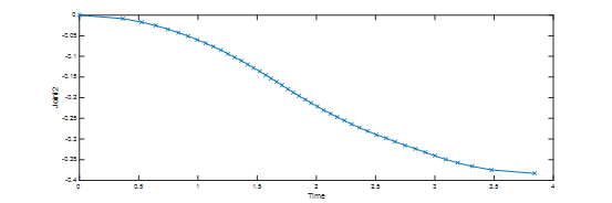

这两个图充分说明moveit产生的轨迹已经是经过插值了的,具体moveit内部插值是怎样插值的我们先不去管他,但从它产生的速度曲线来看,其插值算法并不是很好。简单的两点插值能插成这样也是醉了。这是否跟ROS 1的非实时性有点关系,由于在PC上执行,对时间的把控不是很好?这也是ROS无法真正用于严格的工业环境的原因吧。
好吧,得到了这样的一个插值数据,怎么将其用于控制电机转动呢。我们使用树莓派作为控制器发送脉冲给步进电机来旋转一定的角度。如果在树莓派中能够精确地控制好延时,并正确地在延时时间内发送指定数量的脉冲,那么问题就很好解决了。
————————————————


评论(0)
您还未登录,请登录后发表或查看评论