
先给出一些预备知识:
-
欧拉角:即所谓的Roll , Pitch , Yaw. 而事实上,根据其定义,欧拉角的具有不同的表示。存在先绕哪个轴,后绕哪个轴转的差别(将旋转分解成绕三个轴的转角)。这种表示方法比较直观,但是存在万向锁(Gimbal Lock)问题,也称为奇异性问题。可以参考这个链接进行理解,这里不再赘述 点击这里跳转。
-
四元数:紧凑的,没有奇异性问题,较多在工程中应用。缺点是不够直观。假设某个旋转是绕着单位向量
n
=
[
n
x
,
n
y
,
n
z
]
T
n=[n_x,n_y,n_z]^T
n=[nx,ny,nz]T进行角度为
θ
\theta
θ的旋转,那么这个四元数定义为
q
=
[
c
o
s
θ
2
,
n
x
s
i
n
θ
2
,
n
y
s
i
n
θ
2
,
n
z
s
i
n
θ
2
]
T
q=[cos{\theta \over 2}, n_xsin{\theta \over 2},n_ysin{\theta \over 2},n_zsin{\theta \over 2}]^T
q=[cos2θ,nxsin2θ,nysin2θ,nzsin2θ]T -
轴角法:任意旋转都是用一个旋转轴和一个旋转角来刻画。假设有一个单位旋转轴为
n
n
n,角度为
θ
\theta
θ的旋转,那么它对应的旋转向量为
n
θ
n\theta
nθ。从旋转向量到旋转矩阵的转换过程由 罗德里格斯公式表明。
R
=
c
o
s
θ
I
+
(
1
−
c
o
s
θ
)
n
n
T
+
s
i
n
θ
n
∧
R=cos\theta I + (1-cos\theta)nn^T+sin\theta n^{\land}
R=cosθI+(1−cosθ)nnT+sinθn∧ -
更多参考引用 :
[飞控]姿态误差(四)-APM如何计算姿态误差
[飞控]姿态误差(三)-四元数和轴角求误差
[飞控]姿态误差(一)-欧拉角做差
[飞控]倾转分离(三)-大总结
[飞控]倾转分离(二)-PX4倾转分离,效果验证
[飞控]倾转分离(一)-APM的倾转分离竟然没有效果? -
通过B到A的四元数,根据公式计算出来的是A到B的旋转矩阵!!!
四元数的二义性,从姿态A旋转到姿态B可以存在两种旋转方式,一个绕小圈,一个绕大圈,两个旋转对应的四元数互为相反数。
姿态本质是旋转,姿态的误差其实是旋转之间的误差,那必须还是个旋转,那么直接相减还能表示旋转吗?也就是说相减得到的角度转换成旋转矩阵还是个正交矩阵吗?
而且欧拉角是有隐藏条件的,就是旋转顺序,同样是三个角 (10,20.30) ,x-y-z,y-x-z顺序可是两个不同的旋转,如果我不告诉你它的旋转顺序,那其实它就是没用的三个数,因为它根本就没法还原成旋转。但是我就没见过有对控制器做先后顺序处理的,roll,pitch,yaw的控制器都是同时启动,没有顺序之分。
所以,凭什么姿态误差可以用欧拉角相减!!!
以下摘自“无人机干货铺”原文: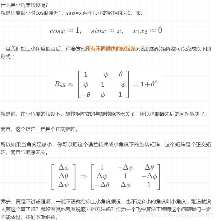
作者缜密的思路,说的简直太漂亮了!
ArduPilot姿态控制
同PX4一样,均采用的是四元数旋转完成姿态的控制。分成两个步骤完成,本次剖析代码如下:
// thrust_heading_rotation_angles - calculates two ordered rotations to move the att_from_quat quaternion to the att_to_quat quaternion.
// The first rotation corrects the thrust vector and the second rotation corrects the heading vector.
void AC_AttitudeControl::thrust_heading_rotation_angles(Quaternion& att_to_quat, const Quaternion& att_from_quat, Vector3f& att_diff_angle, float& thrust_vec_dot)
{
    Matrix3f att_to_rot_matrix; // rotation from the target body frame to the inertial frame.
    att_to_quat.rotation_matrix(att_to_rot_matrix);
    Vector3f att_to_thrust_vec = att_to_rot_matrix _ Vector3f(0.0f, 0.0f, 1.0f);

    Matrix3f att_from_rot_matrix; // rotation from the current body frame to the inertial frame.
    att_from_quat.rotation_matrix(att_from_rot_matrix);
    Vector3f att_from_thrust_vec = att_from_rot_matrix _ Vector3f(0.0f, 0.0f, 1.0f);

    // the dot product is used to calculate the current lean angle for use of external functions
    _thrust_angle = acosf(constrain_float(Vector3f(0.0f,0.0f,1.0f) _ att_from_thrust_vec,-1.0f,1.0f));

    // the cross product of the desired and target thrust vector defines the rotation vector
    Vector3f thrust_vec_cross = att_from_thrust_vec % att_to_thrust_vec;

    // the dot product is used to calculate the angle between the target and desired thrust vectors
    thrust_vec_dot = acosf(constrain_float(att_from_thrust_vec _ att_to_thrust_vec, -1.0f, 1.0f));

    // Normalize the thrust rotation vector
    float thrust_vector_length = thrust_vec_cross.length();
    if (is_zero(thrust_vector_length) || is_zero(thrust_vec_dot)) {
        thrust_vec_cross = Vector3f(0, 0, 1);
        thrust_vec_dot = 0.0f;
    } else {
        thrust_vec_cross /= thrust_vector_length;
    }
    Quaternion thrust_vec_correction_quat;
    thrust_vec_correction_quat.from_axis_angle(thrust_vec_cross, thrust_vec_dot);

    // Rotate thrust_vec_correction_quat to the att_from frame
    thrust_vec_correction_quat = att_from_quat.inverse() _ thrust_vec_correction_quat _ att_from_quat;

    // calculate the remaining rotation required after thrust vector is rotated transformed to the att_from frame
    Quaternion yaw_vec_correction_quat = thrust_vec_correction_quat.inverse() _ att_from_quat.inverse() _ att_to_quat;

    // calculate the angle error in x and y.
    Vector3f rotation;
    thrust_vec_correction_quat.to_axis_angle(rotation);
    att_diff_angle.x = rotation.x;
    att_diff_angle.y = rotation.y;

    // calculate the angle error in z (x and y should be zero here).
    yaw_vec_correction_quat.to_axis_angle(rotation);
    att_diff_angle.z = rotation.z;

    // Todo: Limit roll an pitch error based on output saturation and maximum error.

    // Limit Yaw Error based on maximum acceleration - Update to include output saturation and maximum error.
    // Currently the limit is based on the maximum acceleration using the linear part of the SQRT controller.
    // This should be updated to be based on an angle limit, saturation, or unlimited based on user defined parameters.
    if (!is_zero(_p_angle_yaw.kP()) && fabsf(att_diff_angle.z) > AC_ATTITUDE_ACCEL_Y_CONTROLLER_MAX_RADSS / _p_angle_yaw.kP()) {
        att_diff_angle.z = constrain_float(wrap_PI(att_diff_angle.z), -AC_ATTITUDE_ACCEL_Y_CONTROLLER_MAX_RADSS / _p_angle_yaw.kP(), AC_ATTITUDE_ACCEL_Y_CONTROLLER_MAX_RADSS / _p_angle_yaw.kP());
        yaw_vec_correction_quat.from_axis_angle(Vector3f(0.0f, 0.0f, att_diff_angle.z));
        att_to_quat = att_from_quat _ thrust_vec_correction_quat _ yaw_vec_correction_quat;
    }
}

算法步骤:
1.通过对齐 当前机体坐标系 z 轴 和 期望机体坐标系 z 轴 得到 tilt 误差
2.把 tilt 误差 转到 地理系 或者 转到 机体系
3.总误差 - tilt 误差 = torsion 误差
4.限制 torsion 误差 可以使用「限幅」方法 或者「衰减」方法
5.把限制后的 torsion 和 tilt 组合成新的总误差
注:
- ArduPilot代码中,att_to_thrust_vec 和 att_from_thrust_vec 均是在NED坐标系下,所以采用轴角法得到的tilt是在NED坐标系下,算法中将其旋转到 机体坐标系下进行运算。
- 矩阵乘法在满足算法步骤3的前提下,也要满足坐标系的可以转换前提。针对步骤3,我们设定中间步骤为tb1,可以得到如下的转换关系 (cb->tb1)’ 乘以(N->cb)’ 乘以 (N->tb) ,结果为tb1->tb。上述转换关系需要好好理解。
然后我将代码转换成Matlab进行仿真。
其中蓝色是中间姿态,红色是目标姿态,绿色为初始姿态。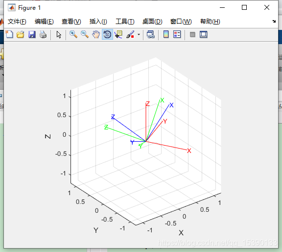
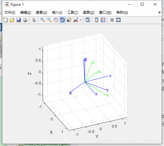
结论为:无论初始姿态和最终姿态给什么样子,均能够较好的跟踪上,但是第一步并没有较好的完成对齐。且ArduPilot飞控在本部分存在问题,最后将第一次选择的z方向给省略了,用第二次的torsion的z来表示最后的Z值,这会存在一定程度上的误差。
//总误差: att_from_quat.inverse()_att_to_quat
//当前姿态的逆_期望姿态 就是 期望姿态-当前姿态的意思 得到的是总误差
//旋转误差: 倾斜误差的逆_总误差 就是 总误差减去倾斜误差的意思 得到的是 剩余的旋转误差
//向量的旋转需要使用四元数旋转公式,四元数的连乘类似于旋转矩阵 可以约去坐标系
注:矩阵乘法有结合律。所以上述注释放在程序中没有问题。
附:无人机干货铺的Matlab代码,我这里仅仅保留PX4的,用来做对比用,后面也会自己做一份。
global x_axis_last;
global y_axis_last;
global z_axis_last;
x_axis_last=[1,0,0];
y_axis_last=[0,1,0];
z_axis_last=[0,0,1];
NED=[0 0 0];
Cur_angle=[10 10 10];
Des_angle=[45 45 45];
%根据 roll pitch yaw 的外环增益 计算 权重
attitude_gain =[6.5 , 6.5 , 2.8];
roll_pitch_gain = (attitude_gain(1) + attitude_gain(2)) / 2.0;
yaw_w = constrain_float(attitude_gain(3) / roll_pitch_gain, 0.0, 1.0)
attitude_gain(3) = roll_pitch_gain;

%弧度
cur_angle_radian=[Cur_angle(1)_pi/180,Cur_angle(2)_pi/180,Cur_angle(3)_pi/180] ;
des_angle_radian=[Des_angle(1)_pi/180,Des_angle(2)_pi/180,Des_angle(3)_pi/180];

%这个画图画的是在以N系为基础的旋转 即 地理坐标系的旋转
plot_body_cur_axis_in_NED([0,0,0],NED,[‘k’,‘k’,‘k’],‘-‘,2)
plot_body_cur_axis_in_NED([0,0,0],Cur_angle,[‘g’,‘g’,‘g’],‘-‘,1)
plot_body_cur_axis_in_NED([0,0,0],Des_angle,[‘r’,‘r’,‘r’],‘-‘,1)

%当前姿态 Ccur->N
cur_dcm= euler2dcm(cur_angle_radian(1),cur_angle_radian(2),cur_angle_radian(3));
q=euler2qual( cur_angle_radian(1),cur_angle_radian(2),cur_angle_radian(3) );
q=Q_normalize(q);
%当前姿态的旋转矩阵 取出z轴列(z轴单位向量) Zcur(N;)
e_z=cur_dcm_[0;0;1];
%期望姿态 Ctar->N
des_dcm = euler2dcm( des_angle_radian(1),des_angle_radian(2),des_angle_radian(3) );
qd=euler2qual( des_angle_radian(1),des_angle_radian(2),des_angle_radian(3) );
qd=Q_normalize(qd);
%期望姿态的旋转矩阵 取出z轴列(z轴单位向量) Ztar(N)
e_z_d=des_dcm_[0;0;1];

%PX4_Q(当前,期望) 得到的是 当前->期望的旋转 Q cur-> tb1
qd_red=PX4_Q(e_z,e_z_d);%%增量 可以加在任何坐标系下 可以等同于机体坐标系下想旋转

if (abs(qd_red(1)) > (1 - 1e-5) || abs(qd_red(2)) > (1 - 1e-5))
    qd_red = qd;
else
    %把转轴 转到N系
    %q(cb->n)^-1 qd_red q(cb->n)
    %把 误差 转到 N系
    %q(cb->n) _  q(cb->n)^-1 qd_red q(cb->n)  = qd_red q(cb->n)
    %得到地理系下的误差 Qtb1-N
    qd_red = Q_multipli(qd_red , q);  %
    % 画出Qtb1在地理系下的坐标
    %plot_body_tar_axis_in_NED_Q([0,0,0],NED ,qd_red ,[‘c’,‘c’,‘c’],‘:’,5)
end

%Qtar->tb1 = Qtb1->n^-1 _ Qtar->n
q_mix = Q_multipli( Q_INV(qd_red) , qd );
% 画出 目标 位置 减去 旋转误差 在地理系下的坐标
%plot_body_tar_axis_in_NED_Q([0,0,0],Des_angle ,Q_INV(q_mix) ,[‘r’,‘r’,‘r’],‘—‘,3)

%优化旋转误差
q_mix = q_mix_signNoZero(q_mix(1));
q_mix(1) = constrain_float(q_mix(1), -1, 1);
q_mix(4) = constrain_float(q_mix(4), -1, 1);

%限制旋转误差  组合成新的旋转 qd= Qtb1->N _ Qtar->tb1 = Qtar->N
qd = Q_multipli( qd_red , [cos(yaw_w _ acos(q_mix(1))), 0, 0, sin(yaw_w * asin(q_mix(4)))]);

%新的 Qtar->cur
qe = Q_multipli( Q_INV(q) , qd) ;

plot_body_tar_axis_in_NED_Q([0,0,0],Cur_angle ,qe ,[‘b’,‘b’,‘b’],‘—‘,3)


评论(0)
您还未登录,请登录后发表或查看评论