

观前提醒,本章主要内容为分析四足机器人步态实现和姿态控制,碰撞体积等程序
步态效果:
一、完整代码如下
# -*- coding: utf-8 -*-

import pybullet as p
import time
import numpy as np

p.connect(p.GUI)
p.createCollisionShape(p.GEOM_PLANE)
p.createMultiBody(0,0)


#Dog robot part shapes
sh_body = p.createCollisionShape(p.GEOM_BOX,halfExtents=[0.45, 0.08, 0.02])
sh_extraweight = p.createCollisionShape(p.GEOM_BOX,halfExtents=[0.45, 0.08, 0.025])
sh_roll = p.createCollisionShape(p.GEOM_BOX,halfExtents=[0.02, 0.02, 0.02])
sh_hip = p.createCollisionShape(p.GEOM_BOX,halfExtents=[0.02, 0.02, 0.02])
sh_knee = p.createCollisionShape(p.GEOM_BOX,halfExtents=[0.02, 0.02, 0.02])
sh_foot = p.createCollisionShape(p.GEOM_SPHERE,radius=0.04)

#The Dog robot is the body with other shapes linked to it
body_Mass = 1
visualShapeId = -1
link_Masses=[.1, .1, .1, .1,
             .1, .1, .1, .1,
             .1, .1, .1, .1,
             .1, .1, .1, .1,
             20]
linkCollisionShapeIndices=[sh_roll, sh_hip, sh_knee, sh_foot,
                           sh_roll, sh_hip, sh_knee, sh_foot,
                           sh_roll, sh_hip, sh_knee, sh_foot,
                           sh_roll, sh_hip, sh_knee, sh_foot,
                           sh_extraweight]
nlnk=len(link_Masses)
linkVisualShapeIndices=[-1]*nlnk    #=[-1,-1,-1, ... , -1]
#link positions wrt the link they are attached to
xhipf=0.4
xhipb=-0.4
yhipl=0.1

xoffh=0.05
yoffh=0.05
hu=0.3
hl=0.3
linkPositions=[[xhipf, yhipl, 0], [xoffh, yoffh, 0], [0, 0, -hu], [0, 0, -hl],
               [xhipf, -yhipl, 0], [xoffh, -yoffh, 0], [0, 0, -hu], [0, 0, -hl],
               [xhipb, yhipl, 0], [xoffh, yoffh, 0], [0, 0, -hu], [0, 0, -hl],
               [xhipb, -yhipl, 0], [xoffh, -yoffh, 0], [0, 0, -hu], [0, 0, -hl],
               [0,0,+0.029]]
linkOrientations=[[0,0,0,1]]*nlnk
linkInertialFramePositions=[[0,0,0]]*nlnk
#Note the orientations are given in quaternions (4 params). There are function to convert of Euler angles and back
linkInertialFrameOrientations=[[0,0,0,1]]*nlnk
#indices determine for each link which other link it is attached to
# for example 3rd index = 2 means that the front left knee jjoint is attached to the front left hip
indices=[0, 1, 2, 3,
         0, 5, 6, 7,
         0, 9,10,11,
         0,13,14,15,
         0]
#Most joint are revolving. The prismatic joints are kept fixed for now
jointTypes=[p.JOINT_REVOLUTE, p.JOINT_REVOLUTE, p.JOINT_REVOLUTE, p.JOINT_PRISMATIC,
            p.JOINT_REVOLUTE, p.JOINT_REVOLUTE, p.JOINT_REVOLUTE, p.JOINT_PRISMATIC,
            p.JOINT_REVOLUTE, p.JOINT_REVOLUTE, p.JOINT_REVOLUTE, p.JOINT_PRISMATIC,
            p.JOINT_REVOLUTE, p.JOINT_REVOLUTE, p.JOINT_REVOLUTE, p.JOINT_PRISMATIC,
            p.JOINT_PRISMATIC]
#revolution axis for each revolving joint
axis=[[1,0,0], [0,1,0], [0,1,0], [0,0,1],
      [1,0,0], [0,1,0], [0,1,0], [0,0,1],
      [1,0,0], [0,1,0], [0,1,0], [0,0,1],
      [1,0,0], [0,1,0], [0,1,0], [0,0,1],
      [0,0,1]]

#Drop the body in the scene at the following body coordinates
basePosition = [0,0,1]
baseOrientation = [0,0,0,1]
#Main function that creates the dog
dog = p.createMultiBody(body_Mass,sh_body,visualShapeId,basePosition,baseOrientation,
                        linkMasses=link_Masses,
                        linkCollisionShapeIndices=linkCollisionShapeIndices,
                        linkVisualShapeIndices=linkVisualShapeIndices,
                        linkPositions=linkPositions,
                        linkOrientations=linkOrientations,
                        linkInertialFramePositions=linkInertialFramePositions,
                        linkInertialFrameOrientations=linkInertialFrameOrientations,
                        linkParentIndices=indices,
                        linkJointTypes=jointTypes,
                        linkJointAxis=axis)
#Due to the weight the prismatic extraweight block needs to be motored up
joint=16
p.setJointMotorControl2(dog,joint,p.POSITION_CONTROL,targetPosition=0.01,force=1000,maxVelocity=3)
#Same for the prismatic feet spheres
joint=3
p.setJointMotorControl2(dog,joint,p.POSITION_CONTROL,targetPosition=0.0,force=1000,maxVelocity=3)
joint=7
p.setJointMotorControl2(dog,joint,p.POSITION_CONTROL,targetPosition=0.0,force=1000,maxVelocity=3)
joint=11
p.setJointMotorControl2(dog,joint,p.POSITION_CONTROL,targetPosition=0.0,force=1000,maxVelocity=3)
joint=15
p.setJointMotorControl2(dog,joint,p.POSITION_CONTROL,targetPosition=0.0,force=1000,maxVelocity=3)

#Add earth like gravity
p.setGravity(0,0,-9.81)
p.setRealTimeSimulation(1)
#Point the camera at the robot at the desired angle and distance
p.resetDebugVisualizerCamera( cameraDistance=1.5, cameraYaw=-30, cameraPitch=-30, cameraTargetPosition=[0.0, 0.0, 0.25])


if (0):
    t0=time.time()
    t=time.time()
    while ((t-t0)<10):
        t=time.time()
    p.disconnect()
    brake

#Scenery e.g. an inclined box
boxHalfLength = 2.5
boxHalfWidth = 2.5
boxHalfHeight = 0.2
sh_colBox = p.createCollisionShape(p.GEOM_BOX,halfExtents=[boxHalfLength,boxHalfWidth,boxHalfHeight])
mass = 1
block=p.createMultiBody(baseMass=0,baseCollisionShapeIndex = sh_colBox,
                        basePosition = [-2,0,-0.1],baseOrientation=[0.0,0.1,0.0,1])


#Add extra lateral friction to the feet spheres
p.changeDynamics(dog,3,lateralFriction=2)
p.changeDynamics(dog,7,lateralFriction=2)
p.changeDynamics(dog,11,lateralFriction=2)
p.changeDynamics(dog,15,lateralFriction=2)


#Function to calculate roll, hip and knee angles from the x,y,z coords of the foot wrt the hip.
def xyztoang(x,y,z,yoffh,hu,hl):
    dyz=np.sqrt(y**2+z**2)
    lyz=np.sqrt(dyz**2-yoffh**2)
    gamma_yz=-np.arctan(y/z)
    gamma_h_offset=-np.arctan(-yoffh/lyz)
    gamma=gamma_yz-gamma_h_offset

    lxzp=np.sqrt(lyz**2+x**2)
    n=(lxzp**2-hl**2-hu**2)/(2*hu)
    beta=-np.arccos(n/hl)

    alfa_xzp=-np.arctan(x/lyz)
    alfa_off=np.arccos((hu+n)/lxzp)
    alfa=alfa_xzp+alfa_off
    if any( np.isnan([gamma,alfa,beta])):
        print(x,y,z,yoffh,hu,hl)
    return [gamma,alfa,beta]


def setlegsxyz(xvec,yvec,zvec,vvec):
    #[a1,a2]=xztoang(xvec[0],zvec[0],1,1)
    a=xyztoang(xvec[0]-xhipf,yvec[0]-yhipl,zvec[0],yoffh,hu,hl)  #(x,y,z,yoffh,hu,hl)
    spd=1
    #any(np.isnan(a))
    joint=0
    p.setJointMotorControl2(dog,joint,p.POSITION_CONTROL,targetPosition=a[0],force=1000,maxVelocity=spd)
    joint=1
    p.setJointMotorControl2(dog,joint,p.POSITION_CONTROL,targetPosition=a[1],force=1000,maxVelocity=vvec[0])
    joint=2
    p.setJointMotorControl2(dog,joint,p.POSITION_CONTROL,targetPosition=a[2],force=1000,maxVelocity=vvec[0])

    a=xyztoang(xvec[1]-xhipf,yvec[1]+yhipl,zvec[1],-yoffh,hu,hl)  #(x,y,z,yoffh,hu,hl)
    spd=1.0
    joint=4
    p.setJointMotorControl2(dog,joint,p.POSITION_CONTROL,targetPosition=a[0],force=1000,maxVelocity=spd)
    joint=5
    p.setJointMotorControl2(dog,joint,p.POSITION_CONTROL,targetPosition=a[1],force=1000,maxVelocity=vvec[1])
    joint=6
    p.setJointMotorControl2(dog,joint,p.POSITION_CONTROL,targetPosition=a[2],force=1000,maxVelocity=vvec[1])

    a=xyztoang(xvec[2]-xhipb,yvec[2]-yhipl,zvec[2],yoffh,hu,hl)  #(x,y,z,yoffh,hu,hl)
    spd=1.0
    joint=8
    p.setJointMotorControl2(dog,joint,p.POSITION_CONTROL,targetPosition=a[0],force=1000,maxVelocity=spd)
    joint=9
    p.setJointMotorControl2(dog,joint,p.POSITION_CONTROL,targetPosition=a[1],force=1000,maxVelocity=vvec[2])
    joint=10
    p.setJointMotorControl2(dog,joint,p.POSITION_CONTROL,targetPosition=a[2],force=1000,maxVelocity=vvec[2])

    a=xyztoang(xvec[3]-xhipb,yvec[3]+yhipl,zvec[3],-yoffh,hu,hl)  #(x,y,z,yoffh,hu,hl)
    spd=1.0
    joint=12
    p.setJointMotorControl2(dog,joint,p.POSITION_CONTROL,targetPosition=a[0],force=1000,maxVelocity=spd)
    joint=13
    p.setJointMotorControl2(dog,joint,p.POSITION_CONTROL,targetPosition=a[1],force=1000,maxVelocity=vvec[3])
    joint=14
    p.setJointMotorControl2(dog,joint,p.POSITION_CONTROL,targetPosition=a[2],force=1000,maxVelocity=vvec[3])

#Pre-init robot position
setlegsxyz([xhipf,xhipf,xhipb,xhipb],[yhipl+0.1,-yhipl-0.1,yhipl+0.1,-yhipl-0.1],[-0.5,-0.5,-0.5,-0.5],[1,1,1,1])
t0=time.time()
t=time.time()
while ((t-t0)<4):
    t=time.time()


#Rotation matrix for yaw only between robot-frame and world-frame
def RotYawr(yawr):
    Rhor=np.array([[np.cos(yawr),-np.sin(yawr),0], [np.sin(yawr),np.cos(yawr),0], [0,0,1]])
    return Rhor

#Init robot position, orientation and pose params
# O means in world-centered coordinates
# R means in robot-centered coordinates
# r is for "of the robot"
# i is initial
yawri=1.3
xrOi=np.array([1,1,0.5])
legsRi=np.array([[xhipf,xhipf,xhipb,xhipb],
               [yhipl+0.1,-yhipl-0.1,yhipl+0.1,-yhipl-0.1],
               [-0.5,-0.5,-0.5,-0.5]])
#Set body to the robot pos
xbOi=xrOi
#Init body position and orientation
quat=p.getQuaternionFromEuler([0,0,yawri])
p.resetBasePositionAndOrientation(dog,xbOi,quat)
#Init leg abs pos
Ryawri=RotYawr(yawri)
legsO=(np.dot(Ryawri,legsRi).T + xbOi).T   #Apply rotation plus translation

#Set the non-initial variables and matrix
yawr=yawri
xrO=xrOi
xbO=xrO
Ryawr=RotYawr(yawri)

#Recalc leg rel pos in robot frame and set the legs
dlegsO=(legsO.T-xbO).T
dlegsR=np.dot(Ryawr.T,dlegsO)
setlegsxyz(dlegsR[0],dlegsR[1],dlegsR[2],[1,1,1,1])

#Calculate a new robot center position from the average of the feet positions
#Calculate a new robot yaw ditrection also from the feet positions
xfO=(legsO[:,0]+legsO[:,1])/2.0
xbO=(legsO[:,2]+legsO[:,3])/2.0
xrOn=(xfO+xbO)/2.0 + np.array([0,0,0.5])
xfmbO=xfO-xbO
yawrn=np.arctan2(xfmbO[1],xfmbO[0])

#Camera paramers to be able to yaw pitch and zoom the camera (Focus remains on the robot)
cyaw=10
cpitch=-15
cdist=1.5

#Walking speed (changes the walking loop time)
walkLoopSpd=400

#Change general motor speed
vvec=[12]*4

#Current leg to change position
l=0
#Init the center for the robot rotation to the current robot pos
xrcO=xrO
#Set the body position to the robot position
xoff=0
yoff=0
#Init to walking fwd
dr=0
drp=0
#Leg sequence (for rotating the robot, I chose to chg legs in the order front-left, fr, br, bl)
lseq=[0,1,3,2]
lseqp=[0,1,3,2]
#lseq=[2,0,3,1]
#lseqp=[2,0,3,1]

while (1):
    cubePos, cubeOrn = p.getBasePositionAndOrientation(dog)
    p.resetDebugVisualizerCamera( cameraDistance=cdist, cameraYaw=cyaw, cameraPitch=cpitch, cameraTargetPosition=cubePos)

    keys = p.getKeyboardEvents()
    #Keys to change camera
    if keys.get(100):  #D
        cyaw+=1
    if keys.get(97):   #A
        cyaw-=1
    if keys.get(99):   #C
        cpitch+=1
    if keys.get(102):  #F
        cpitch-=1
    if keys.get(122):  #Z
        cdist+=.01
    if keys.get(120):  #X
        cdist-=.01
    #Keys to change the robot walk (fwd, bkw, rot right, rot left)
    if keys.get(65297): #Up
        drp=0
    if keys.get(65298): #Down
        drp=2
    if keys.get(65296): #Right
        drp=1
        xrcO=xrO        #Set the center for the robot rotation to the current robot pos
        lseqp=[1,0,2,3] #Change the leg sequence to open up the front arms rather than close them
    if keys.get(65295): #Left
        drp=3
        xrcO=xrO
        lseqp=[0,1,3,2] #Change the leg sequence to open up the front arms rather than close them

    #Time cycle
    tv=int(((time.time()-t0)*walkLoopSpd)  % 800)
    #One leg movement in 200 units. one 4-leg walk cycle in 800 units
    #Using <, >, % (modulo) and divide we can easily do something in a specific part of the cycle

    #Apply new walking cycle type (e.g. chg from fwd to bkw) only at the start of next cycle
    if tv<20 and (not dr==drp):
        dr=drp
        lseq=lseqp

    #Index of the leg to move
    l=int(tv/200)
    #Actual leg to move
    k=lseq[l]

    #In the beginning of the leg cycle the body is centered at the robot center
    #then it gradually moves in the opposite direction of the leg to be moved
    #to ensure the center of gravity remains on the other 3 legs
    #when the moving leg goes down again the body center returns to the robot center
    #The vars xoff and yoff move the body w.r.t. the robot center in the robot frame
    if int(tv%200)<10:
        xoff=0
        yoff=0
    elif int(tv%200)<80:
        xoff+=0.002*(-1+2*int(k/2))  #Work it out on paper to see it moves opposite to the stepping leg
        yoff+=0.002*(-1+2*(k%2))

    elif int(tv%200)>160:
        xoff-=0.004*(-1+2*int(k/2))
        yoff-=0.004*(-1+2*(k%2))

    #Recalc leg rel pos in desired robot frame
    dlegsO=(legsO.T-xrO).T  #Translate
    dlegsR=np.dot(Ryawr.T,dlegsO)  #Rotate (Note the inverse rotation is the transposed matrix)
    #Then apply the body movement and set the legs
    setlegsxyz(dlegsR[0]-xoff-0.03,dlegsR[1]-yoff,dlegsR[2],vvec)  #0.03 is for tweaking the center of grav.


    if int(tv%200)>80:
        dlegsO=(legsO.T-xrcO).T
        yawlO=np.arctan2(dlegsO[1,k],dlegsO[0,k])
        rlO=np.sqrt(dlegsO[0,k]**2+dlegsO[1,k]**2)

        if dr==0:
            legsO[0,k]=rlO*np.cos(yawlO)+xrcO[0]+0.01*np.cos(yawr)
            legsO[1,k]=rlO*np.sin(yawlO)+xrcO[1]+0.01*np.sin(yawr)
        elif dr==1:
            yawlO-=0.015
            legsO[0,k]=rlO*np.cos(yawlO)+xrcO[0]
            legsO[1,k]=rlO*np.sin(yawlO)+xrcO[1]
        elif dr==2:
            legsO[0,k]=rlO*np.cos(yawlO)+xrcO[0]-0.01*np.cos(yawr)
            legsO[1,k]=rlO*np.sin(yawlO)+xrcO[1]-0.01*np.sin(yawr)
        elif dr==3:
            yawlO+=0.015
            legsO[0,k]=rlO*np.cos(yawlO)+xrcO[0]
            legsO[1,k]=rlO*np.sin(yawlO)+xrcO[1]

        if int(tv%200)<150:
            #Move leg k upwards
            legsO[2,k]+=.006
        else:
            #Move leg k wards
            legsO[2,k]-=.006
    else:
        #Move/keep all legs down to the ground
        legsO[2,0]=0.0
        legsO[2,1]=0.0
        legsO[2,2]=0.0
        legsO[2,3]=0.0


    #Calculate vectors and matrix for the next loop
    xfrO=(legsO[:,0]+legsO[:,1])/2.0
    xbkO=(legsO[:,2]+legsO[:,3])/2.0
    xrO=(xfrO+xbkO)/2.0
    xrO[2]=0.5
    xfmbO=xfrO-xbkO
    yawr=np.arctan2(xfmbO[1],xfmbO[0])
    Ryawr=RotYawr(yawr)

    time.sleep(0.01)

p.disconnect()
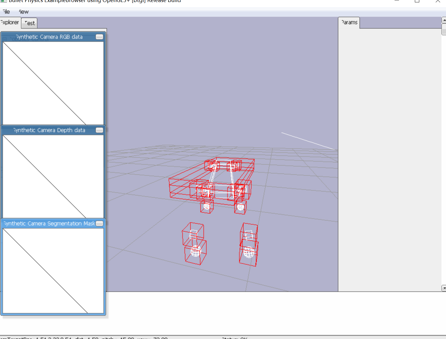
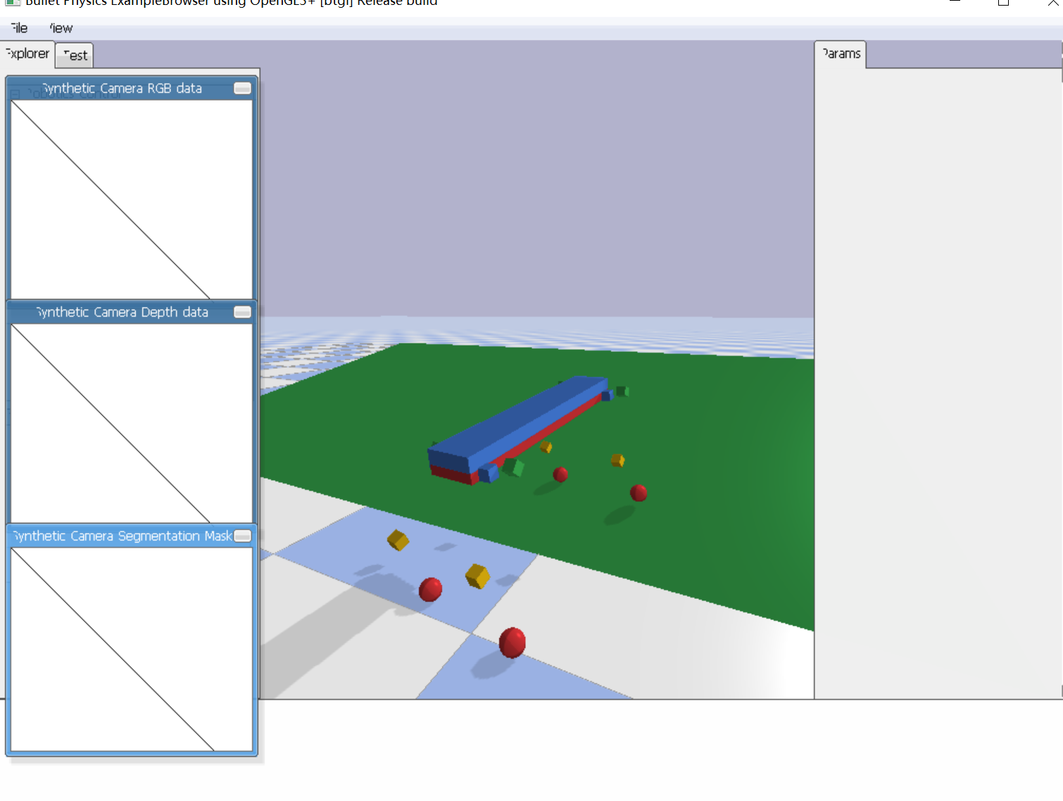
运行上述代码,我们可以看到四足机器人的形态、碰撞体积、基础步态
另外此程序还在场景中仿真了一个斜坡用于测试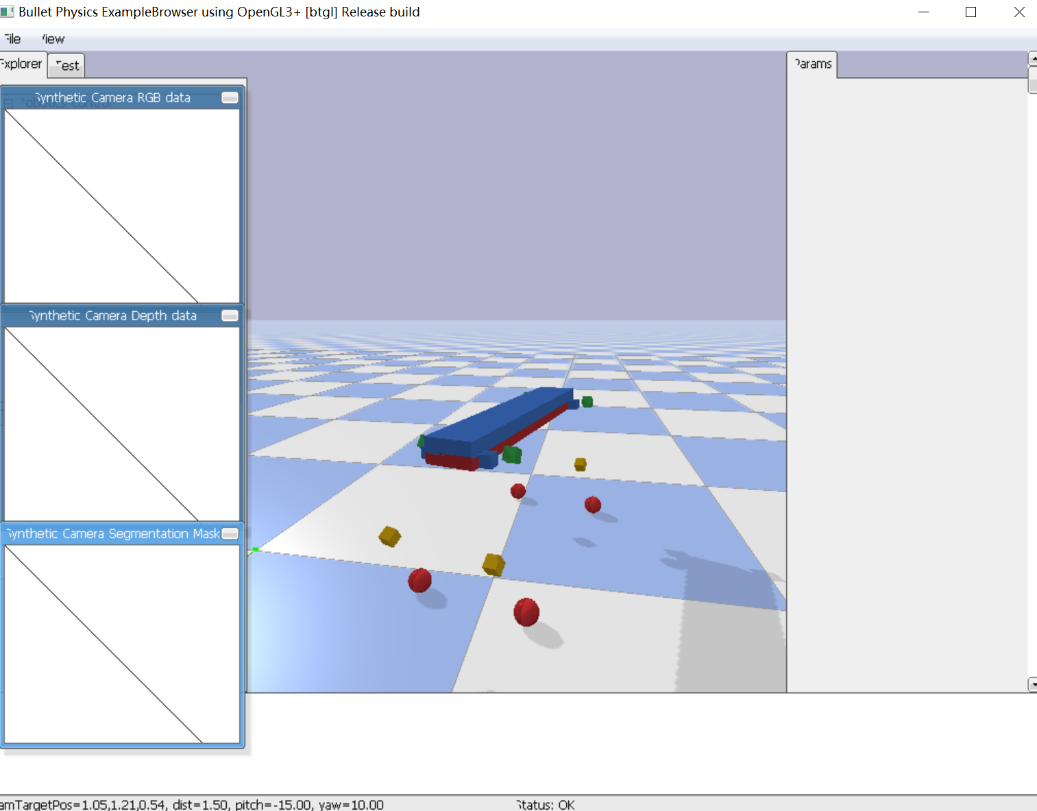
二、代码整体分析
上述代码乍一看十分复杂,其实我们可以将其分为若干部分来依次分析
- 初始化
导入模块:pybullet(物理模拟引擎),time 和 numpy。
连接到pybullet的GUI客户端,创建一个平面几何形状作为地面,并创建一个基础的多体对象。 - 创建机器人部件
为机器人的身体和各个关节定义几何形状,包括身体、额外的重量块、滚轮、髋关节、膝关节和脚(一个球形)。 - 构建机器人
使用 createMultiBody 函数创建了机器人的主体和链接的部分,指定了每个部分的质量、形状、位置和方向。
设置了机器人的关节类型和关节轴,定义了旋转关节和柱状关节。 - 设置动力学和摄像头
为机器人的额外重量块和脚部的柱状关节设置了马达控制,使它们能够移动到指定位置。
添加了类似地球的重力。
设置了实时模拟。
初始化摄像头的位置和角度。 - 环境建设
创建了一个斜面的盒子作为场景的一部分。
为机器人的脚增加了额外的横向摩擦力。 - 动作函数定义
xyztoang:计算从髋关节到脚部的x,y,z坐标到滚轮、髋关节和膝关节角度的转换。
setlegsxyz:根据脚的世界坐标设置每个腿部关节的目标位置。
RotYawr:创建一个绕yaw轴旋转的旋转矩阵。 - 机器人初始化位置和方向
使用 resetBasePositionAndOrientation 函数将机器人的位置和方向设置到初始值。 - 主循环
无限循环,模拟机器人的运动。
读取键盘事件来控制摄像头和机器人的行走方向。
根据时间和预设的速度周期性地移动机器人的腿部,使机器人模拟走路的动作。
计算新的机器人中心位置和朝向,并根据脚的位置更新机器人的方向。 - 控制逻辑
通过键盘输入控制机器人的前进、后退、向右旋转和向左旋转。
根据时间循环来确定何时抬起或放下腿部。 - 清理
在循环的最后,调用 p.disconnect() 断开与物理模拟的连接。
总结来说,这段代码演示了如何在 pybullet 中创建和控制一个简单的四足机器人模型,并且包含了一些基本的用户交互来控制机器人前进和转向。
三、具体核心程序分析
在这个四足机器人仿真程序中,最重要的部分是主循环内的控制逻辑,因为它包含了步态生成、姿态控制、用户输入处理以及机器人与环境的交互。以下分析重点关注程序中实现这些功能的关键代码段。
步态生成和控制:
步态生成的核心在于while (1):这个无限循环中,特别是如何在每一步中计算腿部的移动。以下是步态生成相关的关键代码:
-
时间变量与腿部循环:
tv=int(((time.time()-t0)*walkLoopSpd) % 800)这行代码使用时间来控制步态循环。
tv是一个循环时间变量,它根据程序运行的时间和步态速度walkLoopSpd来计算当前的时间步。这个时间步用于决定机器人腿部的运动阶段。 -
腿部序列和移动:
l=int(tv/200)
k=lseq[l]
这两行代码决定了当前应该移动哪一只腿。
l是当前步态循环的阶段,通过tv除以200(一个腿部运动周期的时间单位)来确定。k是实际移动的腿的索引,由腿部序列lseq决定。 -
腿部姿态调整:
setlegsxyz(dlegsR[0]-xoff-0.03,dlegsR[1]-yoff,dlegsR[2],vvec)`setlegsxyz函数用于设置腿部的目标位置。xoff和yoff变量用于根据重心需要在机器人身体内进行微调,以保持平衡。
姿态控制:
姿态控制涉及机器人身体的平衡和方向,关键代码如下:
-
重心平衡:
xoff += 0.002*(-1+2*int(k/2))
yoff += 0.002*(-1+2*(k%2))
这部分代码用于调整机器人身体的位置,以平衡正在移动的腿的重量。
xoff和yoff的调整是为了保持机器人不会因为一只腿抬起而失去平衡。 -
方向调整:
if dr == 0:
    # code to move forward
elif dr == 1:
    # code to turn right
elif dr == 2:
    # code to move backward
elif dr == 3:
    # code to turn left
这里的代码根据
dr变量的值来调整机器人的行进方向。dr代表不同的运动模式,如前进、后退、右转和左转。
用户输入处理:
处理用户输入允许在仿真中实时控制机器人的行为,关键代码如下:
-
键盘事件监听:
keys = p.getKeyboardEvents()这行代码监听键盘事件,并将按键信息存储在
keys字典中,用于后续处理用户的输入。 -
实时相机控制:
if keys.get(100):  # D
    cyaw += 1
if keys.get(97):   # A
    cyaw -= 1
这部分代码通过监听特定键盘按键来调整摄像头的偏航角度(
cyaw),从而在仿真中改变视角。
机器人与环境交互:
机器人需要在这个四足机器人仿真程序中,最重要的部分是主控制循环,这是仿真运行时持续执行的部分,负责处理步态算法、姿态控制、用户输入和环境交互。在这个循环中,机器人的行为根据一系列计算和条件判断被动态地调整。
步态控制和姿态调整
主循环包含了步态控制的逻辑,这是通过控制每条腿的移动来实现的。步态控制的关键函数是setlegsxyz,它根据腿的目标x, y, z位置来调整腿部关节的角度。
setlegsxyz(dlegsR[0]-xoff-0.03,dlegsR[1]-yoff,dlegsR[2],vvec)
在这里,setlegsxyz调用了xyztoang函数来计算每个关节应该达到的角度,以便将腿移动到指定位置。xoff和yoff是根据机器人当前步态周期内腿的移动而动态调整的偏移量,用于保持机器人的平衡。
a=xyztoang(xvec[0]-xhipf,yvec[0]-yhipl,zvec[0],yoffh,hu,hl)
xyztoang是一个关键的逆运动学函数,它根据脚的世界坐标计算出关节的目标角度。逆运动学是步态控制中至关重要的数学工具,因为它允许我们从目标脚步位置反向工作出必要的关节角度。
用户输入处理
用户输入处理允许实时控制机器人的行为和仿真相机的视角。通过监听键盘事件,程序可以响应用户的命令,实现机器人的行走和方向转换。
keys = p.getKeyboardEvents()
这段代码捕捉键盘事件,并在主循环中进行处理。例如,以下代码片段响应用户的上、下、左、右按键来控制机器人的移动方向。
if keys.get(65297): #Up
    drp=0
if keys.get(65298): #Down
    drp=2
if keys.get(65296): #Right
    drp=1
if keys.get(65295): #Left
    drp=3
环境交互
机器人与环境的交互是通过pybullet物理引擎实现的。程序设置了重力并根据机器人的运动和环境中的物理规则进行计算。例如,以下代码设置了仿真的重力:
p.setGravity(0,0,-9.81)
设定重力是模拟现实世界条件的关键部分,影响机器人的步态表现和稳定性。
实时仿真和相机控制
程序还包括实时仿真的启动以及相机的控制,这对于用户来说是观察和评估机器人行为的重要部分。
p.setRealTimeSimulation(1)
通过启动实时仿真,用户可以看到机器人根据物理规则在环境中移动。
总结来说,仿真的核心是主控制循环,它集成了步态算法、姿态调整、用户输入处理和环境交互。这些组合起来形成了一个复杂的系统,使机器人能够在虚拟环境中以现实世界的物理规则行走和响应。
四、机器人模型创建
- 创建碰撞形状:使用p.createCollisionShape函数创建机器人各部分的碰撞形状。这些形状将用于物理引擎中的碰撞检测。
sh_body: 机器人身体的碰撞形状,为一个长方体。
sh_extraweight: 机器人用于模拟额外重量的碰撞形状,也是一个长方体。
sh_roll, sh_hip, sh_knee: 分别为机器人的滚轮、髋关节和膝关节部分的碰撞形状,都是小长方体。
sh_foot: 机器人脚部的碰撞形状,为一个球体。 - 定义机器人主体和链接属性:
body_Mass: 机器人身体的质量。
visualShapeId: 视觉形状的ID,这里设置为-1,表示不使用视觉形状。
link_Masses: 机器人各个连接部分的质量数组。
linkCollisionShapeIndices: 与link_Masses对应,这个数组定义了每个连接部分的碰撞形状索引。
nlnk: 链接的数量,由link_Masses数组的长度决定。
linkVisualShapeIndices: 视觉形状索引的数组,这里都设置为-1,表示不使用视觉形状。 - 设置关节和连接信息:
linkPositions: 定义链接相对于它们所附着的部分的位置。
linkOrientations: 定义链接的方向,这里使用四元数表示。
linkInertialFramePositions: 定义链接的惯性框架位置,这里都设置为原点。
linkInertialFrameOrientations: 定义链接的惯性框架方向,使用四元数表示。
indices: 定义每个链接附着到的其他链接的索引。
jointTypes: 定义每个关节的类型,大多数是旋转关节(p.JOINT_REVOLUTE),有些是棱柱关节(p.JOINT_PRISMATIC)但被固定不动。
axis: 定义每个旋转关节的旋转轴。
五、步态实现和姿态控制分析
步态实现:
步态的实现主要通过以下几个部分:
-
腿部运动函数:xyztoang和setlegsxyz是两个关键函数,它们负责根据期望的脚部位置计算并设置腿部关节的目标角度。
xyztoang函数接收脚部坐标x, y, z和腿部参数,然后计算出滚动、髋部和膝盖的角度。这些角度是通过逆运动学得到的,即根据脚部的目标位置来算出每个关节应该达到的角度。
setlegsxyz函数用于将xyztoang函数计算出的角度应用到机器人模型的关节上,通过p.setJointMotorControl2函数来控制关节达到指定的目标角度。 -
行走循环:在while (1)的主循环中,程序通过一个时间变量tv来控制机器人的步态周期。这个变量在每个循环中更新,并用于确定哪一只腿应该移动以及它们移动的阶段。
-
腿部序列:程序通过一个腿部序列lseq来决定腿部移动的顺序。这个序列确保每次只有一只腿在空中移动,而其他三只腿支撑机器人的重量,维持平衡。
-
腿部位置调整:机器人行走时,腿部会根据周期性的模式进行抬起和放下。当一只腿抬起时,身体的重心会向剩下支撑的三只腿偏移,以保持平衡。这是通过调整xoff和yoff变量完成的,这两个变量会在每个步态周期中逐渐增加或减少,从而移动机器人的身体。
姿态控制:
姿态控制涉及到机器人身体的旋转和平衡,以及对环境变化的适应。在该程序中,姿态控制主要通过以下几个部分实现:
-
姿态初始化:在循环开始前,程序通过p.resetBasePositionAndOrientation函数设置机器人的初始位置和方向。
-
旋转矩阵:程序定义了一个RotYawr函数来计算只有偏航角(Yaw)变化时机器人的旋转矩阵。这个矩阵用于在机器人坐标系和世界坐标系之间转换腿部位置。
-
重心计算:程序通过计算所有脚部平均位置来确定机器人的重心,并据此调整身体的位置,使重心保持在支撑腿的中心区域。
-
方向控制:机器人的行进方向通过计算前后脚之间的向量决定,程序中通过np.arctan2计算偏航角yawr来调整机器人的朝向。
-
响应键盘输入:程序还可以根据键盘输入来改变机器人的移动方向,例如前进、后退、向右旋转和向左旋转。当接收到这些输入时,程序会相应地调整腿部目标位置,从而改变机器人的行走方向。
姿态控制也在循环中不断调整,以响应步态变化和外部输入,确保机器人在移动过程中的稳定性和导向控制。姿态的调整通过改变机器人身体的偏航角、平移和重心来实现。
步态和姿态控制的协同工作:
-
同步调整:步态循环和姿态控制需要同步工作。例如,当一只腿抬起时,身体的重心需要适当偏移,以保持稳定。这需要步态控制和姿态控制紧密协作。
-
动态平衡:在机器人行走时,不仅要控制腿部的运动,还要实时调整机器人的姿态来维持动态平衡。
-
环境交互:程序通过pybullet的物理引擎与仿真环境交互。机器人的步态和姿态会受到仿真环境中的重力、摩擦力和其他物体的影响。
-
反馈控制:通过不断计算机器人的实际位置和方向,程序可以实现反馈控制,即根据当前状态调整步态和姿态来达到预期的运动效果。


评论(0)
您还未登录,请登录后发表或查看评论