

在学习之前需要了解一下坐标系和坐标变换transform,tf的内容。
一步一步的学习URDF
用URDF从零开始构建一个机器人模型
让机器人模型在rviz中可视化
先建立一个简单的模型
先建立一个包用来学习
catkin_create_pkg myurdf controller_manager joint_state_controller robot_state_publisher在包里新建一个文件夹用来保存URDF文件
mkdir robot建立一个只有一个几何体的模型文件
gedit myfirstrobot.urdf输入以下内容,保存。
<?xml version="1.0"?>
<robot name="myfirstrobot">
  <!-- Base Link -->
  <link name="base_link">
    <visual>
      <geometry>
        <box size="0.1 0.1 2"/>
      </geometry>
    </visual>
  </link>
</robot>
把这段话翻译成汉语就是什么呢,你猜?其实就是定义了一个长 ,宽y ,高z 的长方体。
机器人模型的可视化
下面我们想办法观察一下建立的机器人模型是什么样的。
在包下新建一个launch文件夹,保存启动文件。新建一个display.launch文件。输入以下内容
<launch>
  <param
    name="robot_description"
    textfile="$(find myurdf)/robot/myfirstrobot.urdf" />

  <!-- send fake joint values -->
  <node
    name="joint_state_publisher"
    pkg="joint_state_publisher"
    type="joint_state_publisher">
    <param name="use_gui" value="TRUE"/>
  </node>

  <!-- Combine joint values -->
  <node
    name="robot_state_publisher"
    pkg="robot_state_publisher"
    type="state_publisher" />
  <node
    name="rviz"
    pkg="rviz"
    type="rviz"
    respawn="false"
    output="screen"
    args="-d $(find myurdf)/urdf.rviz" />
</launch>
运行下列命令启动
roslaunch myurdf display.launch可以观察到定义的模型是一个细长的长方体,如下图
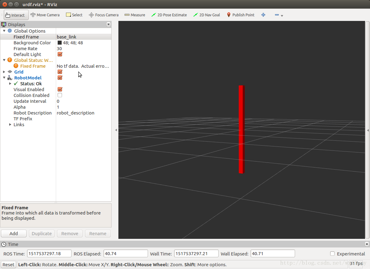
模型坐标系的原点默认在模型的中心,所以就显示成了这个样子。
多个连杆的组装
我们再增加一个连杆
<?xml version="1.0"?>
<robot name="myfirstrobot">
    <!-- Base Link -->
    <link name="base_link">
        <visual>
            <geometry>
                <box size="0.1 0.1 2"/>
            </geometry>
        </visual>
    </link>

    <joint name="joint1" type="fixed">
        <parent link="base_link"/>
        <child link="middle_link"/>
    </joint>

    <link name="middle_link">
        <visual>
            <geometry>
                <box size="0.2 0.2 1"/>
            </geometry>
        </visual>
    </link>

</robot>
URDF好像只有一个根节点,加入另一个连杆之后,就要定义一个joint确定两个连杆之间的关系,一个是父节点一个是子节点。可以看到下图的界面
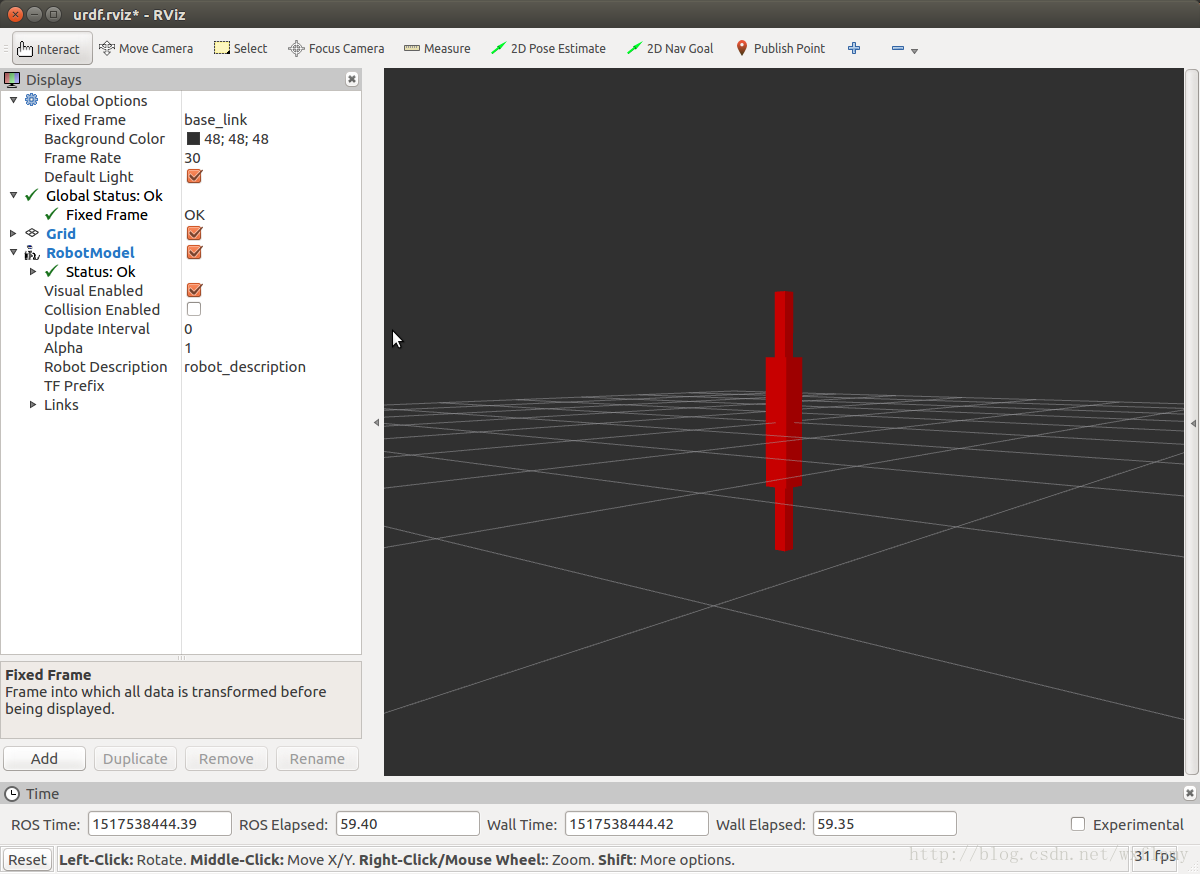
两个叠在一起,显然没有连杆机器人的样子。下面我们得定义连杆和关节的原点以及他们之间的关系,来改变他们之间的相对关系了。
机器人模型的源码就修改成了如下的内容
<?xml version="1.0"?>
<robot name="myfirstrobot">
<!-- Base Link -->
<link name="base_link">
<visual>
<geometry>
<box size="0.1 0.1 2"/>
</geometry>
</visual>
</link>
<joint name="joint1" type="continuous">
<parent link="base_link"/>
<child link="middle_link"/>
<origin rpy="0 0 0" xyz="0 0 1"/>
<axis xyz="0 1 0"/>
</joint>
<link name="middle_link">
<visual>
<geometry>
<box size="0.2 0.2 1"/>
</geometry>
<origin rpy="0 1.57075 0" xyz="0.5 0 0"/>
</visual>
</link>
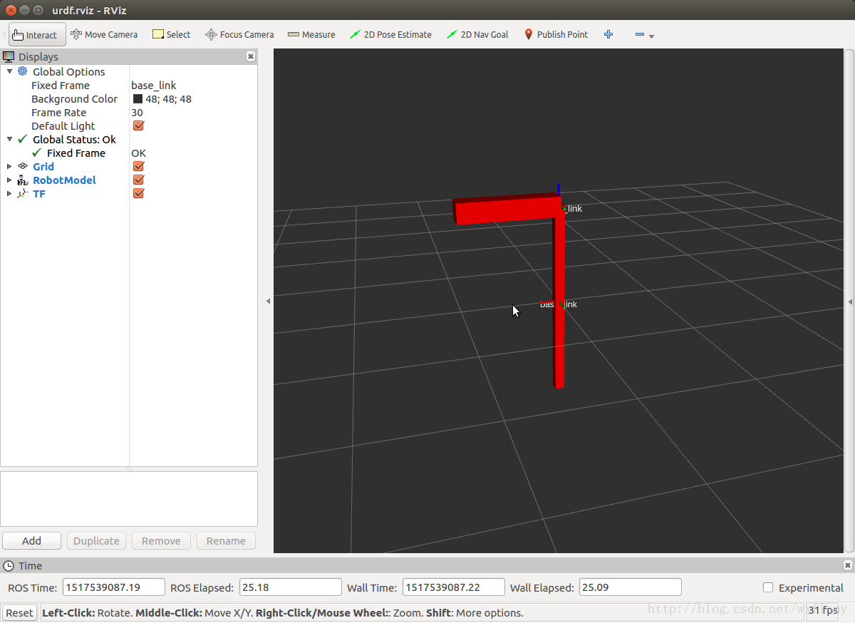
</robot>最后机器人模型的效果是这样的
需要注意的有如下几点
- joint中的x,y,z和r,p,y定义的是子link坐标系在父link坐标系中的位置和朝向,如果都为零,则子link与父link的坐标系保持一致;
- 子link标签的origin里的x,y,z和r,p,y是在使用了joint节点后,link本身在joint坐标系下的旋转和平移,只改变link相对于joint的位置,不改变joint坐标系的朝向和位置。
- 所有变换都是先旋转再平移
- URDF文件加载之后通过tf发布的是joint之间的坐标,也就是图中base_link和middl_link表示的都是连杆所在坐标原点也就是joint的坐标。如果tf找不到这样的坐标,那么模型就是白色的。
- 关节有主要的几种类型:
- fixed:固定关节
- continuous:连续关节,像轮子一样从负无穷到正无穷旋转
- revolute:有限制的旋转,需要设置角度的上下限、速度的上限、作用力矩的上限等
- prismatic:有限制的平移,需要设置距离的上下限、速度的上限、作用力的上限等
这里我们暂时定义了continuous类型的关节。
机器人模型的材料颜色
我们的机器人不想是红色的,红色的是默认强加给我的,怎么改呢
<?xml version="1.0"?>
<robot name="myfirstrobot">
    <material name="blue">
        <color rgba="0 0 0.8 1"/>
    </material>

    <material name="white">
        <color rgba="1 1 1 1"/>
    </material>

    <!-- Base Link -->
    <link name="base_link">
        <visual>
            <geometry>
                <box size="0.1 0.1 2"/>
            </geometry>
            <material name="blue"/>
        </visual>
    </link>

    <joint name="joint1" type="continuous">
        <parent link="base_link"/>
        <child link="middle_link"/>
        <origin rpy="0 0 0" xyz="0 0 1"/>
        <axis xyz="0 1 0"/>
    </joint>

    <link name="middle_link">
        <visual>
            <geometry>
                <box size="0.2 0.2 1"/>
            </geometry>
            <origin rpy="0 1.57075 0" xyz="0.5 0 0"/>
            <material name="white"/>
        </visual>
    </link>

</robot>
再增加一个关节和连杆
其他的稍微调整了一下
<?xml version="1.0"?>
<robot name="myfirstrobot">
    <material name="blue">
        <color rgba="0 0 0.8 0.6"/>
    </material>

    <material name="white">
        <color rgba="1 1 1 0.6"/>
    </material>

  <material name="orange">
    <color rgba="1 0.4 0.1 0.6"/>
  </material>

    <!-- Base Link -->
    <link name="base_link">
        <visual>
            <geometry>
                <box size="0.1 0.1 2"/>
            </geometry>
            <origin rpy="0 0 0" xyz="0 0 1"/>
            <material name="blue"/>
        </visual>
    </link>

    <joint name="joint1" type="continuous">
        <parent link="base_link"/>
        <child link="middle_link"/>
        <origin rpy="0 0 0" xyz="0 0 2"/>
        <axis xyz="0 1 0"/>
    </joint>

    <link name="middle_link">
        <visual>
            <geometry>
                <box size="0.1 0.1 1"/>
            </geometry>
            <origin rpy="0 1.57075 0" xyz="0.5 0 0"/>
            <material name="white"/>
        </visual>
    </link>

    <joint name="joint2" type="continuous">
        <parent link="middle_link"/>
        <child link="top_link"/>
        <origin rpy="0 0 0" xyz="1 0 0"/>
        <axis xyz="0 1 0"/>
    </joint>

    <link name="top_link">
        <visual>
            <geometry>
                <box size="0.1 0.1 1"/>
            </geometry>
            <origin rpy="0 1.57075 0" xyz="0.5 0 0"/>
            <material name="orange"/>
        </visual>
    </link>

    <joint name="end" type="fixed">
        <parent link="top_link"/>
        <child link="end_link"/>
        <origin rpy="0 0 0" xyz="1 0 0"/>
    </joint>

    <link name="end_link">
        <visual>
            <geometry>
                <sphere radius="0.1"/>
            </geometry>
            <material name="white"/>
        </visual>
    </link>
</robot>
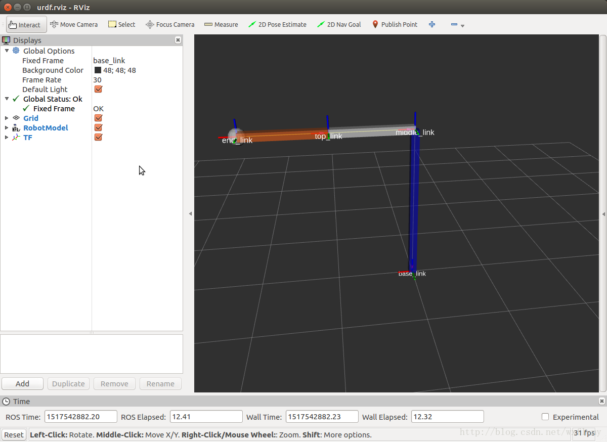
这就是个二连杆机器人了。视觉上的。
定义可以运动的关节
上面我们把关节的类型都设成了type="continuous"的,现在单独讨论以下关节的设置。二连杆中关节当然都是旋转类型的,可以无限旋转,所以设为continuous类型。但是有的机器人旋转是要有限制的,比如末端手柄,这里只做个例子。
    <joint name="end" type="revolute">
        <axis xyz="1 0 0"/>
        <limit effort="1000.0" lower="0.0" upper="0.548" velocity="0.5"/>
        <parent link="top_link"/>
        <child link="end_link"/>
        <origin rpy="0 0 0" xyz="1 0 0"/>
    </joint>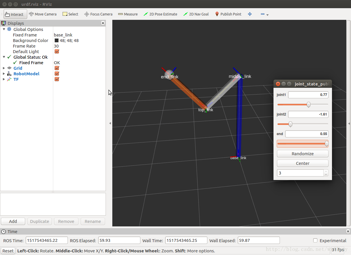
添加物理碰撞属性
主要是为连杆添加碰撞和转动惯量属性,为关节添加动力学属性
添加碰撞属性
以上,每个连杆link的子元素只有视觉上的visual,如果要进行碰撞检测或是在Gazebo中进行仿真的话,就需要定义碰撞属性了。
我用下面这样定义,用一个圆柱把原来的长条给包起来
    <!-- Base Link -->
    <link name="base_link">
        <visual>
            <geometry>
                <box size="0.1 0.1 2"/>
            </geometry>
            <origin rpy="0 0 0" xyz="0 0 1"/>
            <material name="blue"/>
        </visual>
        <collision>
            <geometry>
                <cylinder length="2" radius="0.2"/>
            </geometry>
        </collision>
    </link>
碰撞模型可以个视觉模型设成一样的,有以下两点注意:
- 为了提高碰撞检测的速度,可以将碰撞的模型设成简单的几何体;
- 为了设置安全区,可以将碰撞模型的大小设的略大一些
物理属性
主要是质量和转动惯量
    <!-- Base Link -->
    <link name="base_link">
        <visual>
            <geometry>
                <box size="0.1 0.1 2"/>
            </geometry>
            <origin rpy="0 0 0" xyz="0 0 1"/>
            <material name="blue"/>
        </visual>
        <collision>
            <geometry>
                <cylinder length="2" radius="0.2"/>
            </geometry>
        </collision>
        <inertial>
      <origin xyz="0 0 1" rpy="0 0 0"/>
      <mass value="1"/>
      <inertia
                ixx="0.3342" ixy="0.0" ixz="0.0"
                iyy="0.3342" iyz="0.0"
                izz="0.0017"/>
        </inertial>
    </link>
质量的单位是千克kg,3 的惯性矩阵是对称的,所以只需要六个元素就可以了
接触系数
也可以定义当机器人模型与其他物体发生接触时,应该如何反应,有三个参数:
- mu :摩擦系数
- kp:刚度系数
- kd:阻尼系数
关节动力学
有两个属性:
- 摩擦力,friction:对于平移单位是牛顿,对于旋转单位是牛米
- 阻尼,damping:对于平移
,对于旋转
。
如果没特殊说明,这些都被设为0。
urdf文件最后为:
<?xml version="1.0"?>
<robot name="myfirstrobot">
    <material name="blue">
        <color rgba="0 0 0.8 0.6"/>
    </material>

    <material name="white">
        <color rgba="1 1 1 0.6"/>
    </material>

  <material name="orange">
    <color rgba="1 0.4 0.1 0.6"/>
  </material>

    <!-- Base Link -->
    <link name="base_link">
        <visual>
            <geometry>
                <box size="0.1 0.1 2"/>
            </geometry>
            <origin rpy="0 0 0" xyz="0 0 1"/>
            <material name="blue"/>
        </visual>
        <collision>
            <geometry>
                <cylinder length="2" radius="0.2"/>
            </geometry>
            <origin rpy="0 0 0" xyz="0 0 1"/>
        </collision>
        <inertial>
      <origin xyz="0 0 1" rpy="0 0 0"/>
      <mass value="1"/>
      <inertia
                ixx="0.3342" ixy="0.0" ixz="0.0"
                iyy="0.3342" iyz="0.0"
                izz="0.0017"/>
        </inertial>
    </link>

    <joint name="joint1" type="continuous">
        <parent link="base_link"/>
        <child link="middle_link"/>
        <origin rpy="0 0 0" xyz="0 0 2"/>
        <axis xyz="0 1 0"/>
    </joint>

    <link name="middle_link">
        <visual>
            <geometry>
                <box size="0.1 0.1 1"/>
            </geometry>
            <origin rpy="0 1.57075 0" xyz="0.5 0 0"/>
            <material name="white"/>
        </visual>
        <collision>
            <geometry>
                <cylinder length="1" radius="0.2"/>
            </geometry>
            <origin rpy="0 1.57075 0" xyz="0.5 0 0"/>
        </collision>
        <inertial>
      <origin xyz="0.5 0 0" rpy="0 0 0"/>
      <mass value="1"/>
      <inertia
                ixx="0.0017" ixy="0.0" ixz="0.0"
                iyy="0.085" iyz="0.0"
                izz="0.085"/>
        </inertial>
    </link>

    <joint name="joint2" type="continuous">
        <parent link="middle_link"/>
        <child link="top_link"/>
        <origin rpy="0 0 0" xyz="1 0 0"/>
        <axis xyz="0 1 0"/>
    </joint>

    <link name="top_link">
        <visual>
            <geometry>
                <box size="0.1 0.1 1"/>
            </geometry>
            <origin rpy="0 1.57075 0" xyz="0.5 0 0"/>
            <material name="orange"/>
        </visual>
        <collision>
            <geometry>
                <cylinder length="1" radius="0.2"/>
            </geometry>
            <origin rpy="0 1.57075 0" xyz="0.5 0 0"/>
        </collision>
        <inertial>
      <origin xyz="0.5 0 0" rpy="0 0 0"/>
      <mass value="1"/>
      <inertia
                ixx="0.0017" ixy="0.0" ixz="0.0"
                iyy="0.085" iyz="0.0"
                izz="0.085"/>
        </inertial>
    </link>

    <joint name="end" type="revolute">
        <axis xyz="1 0 0"/>
        <limit effort="1000.0" lower="0.0" upper="0.548" velocity="0.5"/>
        <parent link="top_link"/>
        <child link="end_link"/>
        <origin rpy="0 0 0" xyz="1 0 0"/>
    </joint>

    <link name="end_link">
        <visual>
            <geometry>
                <sphere radius="0.1"/>
            </geometry>
            <material name="white"/>
        </visual>
        <collision>
            <geometry>
                <sphere radius="0.15"/>
            </geometry>
        </collision>
        <inertial>
      <origin xyz="0 0 0" rpy="0 0 0"/>
      <mass value="1"/>
      <inertia
                ixx="0.0017" ixy="0.0" ixz="0.0"
                iyy="0.0017" iyz="0.0"
                izz="0.0017"/>
        </inertial>
    </link>
</robot>
使用Xacro宏让URDF文件变得简洁一些
使用xacro可以做三件事
- 使用常数
- 使用简单的数学计算
- 使用宏
我们新建一个myfirstrobot.xacro文件。有很多可以用的属性,特别是宏,可以整个模块都用宏,可以参考
http://wiki.ros.org/urdf/Tutorials/Using%20Xacro%20to%20Clean%20Up%20a%20URDF%20File
下面宏用的不多,基本没用
<?xml version="1.0"?>
<robot name="myfirstrobot" xmlns:xacro="http://www.ros.org/wiki/xacro">

  <!-- Constants for robot dimensions -->
  <xacro:property name="PI" value="3.1415926535897931"/>
  <xacro:property name="mass" value="1" /> <!-- arbitrary value for mass -->
  <xacro:property name="width" value="0.1" /> <!-- Square dimensions (widthxwidth) of beams -->
  <xacro:property name="height1" value="4" /> <!-- Link 1 -->
  <xacro:property name="height2" value="2" /> <!-- Link 2 -->
  <xacro:property name="height3" value="1" /> <!-- Link 3 -->

    <!-- Import Rviz colors -->
  <xacro:include filename="$(find myurdf)/robot/materials.xacro" />

    <!-- Base Link -->
    <link name="base_link">
        <visual>
            <geometry>
                <box size="${width} ${width} ${height1}"/>
            </geometry>
            <origin rpy="0 0 0" xyz="0 0 ${height1/2}"/>
            <material name="blue"/>
        </visual>
        <collision>
            <geometry>
                <cylinder length="${height1}" radius="${width+0.1}"/>
            </geometry>
            <origin rpy="0 0 0" xyz="0 0 ${height1/2}"/>
        </collision>
        <inertial>
      <origin xyz="0 0 ${height1/2}" rpy="0 0 0"/>
      <mass value="${mass}"/>
      <inertia
            ixx="${mass / 12.0 * (width*width + height1*height1)}" ixy="0.0" ixz="0.0"
            iyy="${mass / 12.0 * (height1*height1 + width*width)}" iyz="0.0"
            izz="${mass / 12.0 * (width*width + width*width)}"/>
        </inertial>
    </link>

    <joint name="joint1" type="continuous">
        <parent link="base_link"/>
        <child link="middle_link"/>
        <origin rpy="0 0 0" xyz="0 0 ${height1}"/>
        <axis xyz="0 1 0"/>
    </joint>

    <link name="middle_link">
        <visual>
            <geometry>
                <box size="${width} ${width} ${height2}"/>
            </geometry>
            <origin rpy="0 ${PI/2} 0" xyz="${height2/2} 0 0"/>
            <material name="white"/>
        </visual>
        <collision>
            <geometry>
                <cylinder length="${height2}" radius="${width+0.1}"/>
            </geometry>
            <origin rpy="0 ${PI/2} 0" xyz="${height2/2} 0 0"/>
        </collision>
        <inertial>
      <origin xyz="${height2/2} 0 0" rpy="0 0 0"/>
      <mass value="${mass}"/>
      <inertia
            ixx="${mass / 12.0 * (width*width + width*width)}" ixy="0.0" ixz="0.0"
            iyy="${mass / 12.0 * (height2*height2 + width*width)}" iyz="0.0"
            izz="${mass / 12.0 * (width*width + height2*height2)}"/>
        </inertial>
    </link>

    <joint name="joint2" type="continuous">
        <parent link="middle_link"/>
        <child link="top_link"/>
        <origin rpy="0 0 0" xyz="${height2} 0 0"/>
        <axis xyz="0 1 0"/>
    </joint>

    <link name="top_link">
        <visual>
            <geometry>
                <box size="${width} ${width} ${height3}"/>
            </geometry>
            <origin rpy="0 ${PI/2} 0" xyz="${height3/2} 0 0"/>
            <material name="orange"/>
        </visual>
        <collision>
            <geometry>
                <cylinder length="${height3}" radius="${width+0.1}"/>
            </geometry>
            <origin rpy="0 ${PI/2} 0" xyz="${height3/2} 0 0"/>
        </collision>
        <inertial>
      <origin xyz="${height3/2} 0 0" rpy="0 0 0"/>
      <mass value="${mass}"/>
      <inertia
            ixx="${mass / 12.0 * (width*width + width*width)}" ixy="0.0" ixz="0.0"
            iyy="${mass / 12.0 * (height3*height3 + width*width)}" iyz="0.0"
            izz="${mass / 12.0 * (width*width + height3*height3)}"/>
        </inertial>
    </link>

    <joint name="end" type="revolute">
        <axis xyz="1 0 0"/>
        <limit effort="1000.0" lower="0.0" upper="0.548" velocity="0.5"/>
        <parent link="top_link"/>
        <child link="end_link"/>
        <origin rpy="0 0 0" xyz="${height3} 0 0"/>
    </joint>

    <link name="end_link">
        <visual>
            <geometry>
                <sphere radius="${width}"/>
            </geometry>
            <material name="white"/>
        </visual>
        <collision>
            <geometry>
                <sphere radius="${width+0.05}"/>
            </geometry>
        </collision>
        <inertial>
      <origin xyz="0 0 0" rpy="0 0 0"/>
      <mass value="${mass}"/>
      <inertia
            ixx="${mass / 12.0 * (width*width + width*width)}" ixy="0.0" ixz="0.0"
            iyy="${mass / 12.0 * (width*width + width*width)}" iyz="0.0"
            izz="${mass / 12.0 * (width*width + width*width)}"/>
        </inertial>
    </link>
</robot>需要再定义个xacro的启动文件display_xacro.launch
<launch>
<param
name="robot_description"
command="$(find xacro)/xacro --inorder '$(find myurdf)/robot/myfirstrobot.xacro'" />
<!-- send fake joint values -->
<node
name="joint_state_publisher"
pkg="joint_state_publisher"
type="joint_state_publisher">
<param name="use_gui" value="TRUE"/>
</node>
<!-- Combine joint values -->
<node
name="robot_state_publisher"
pkg="robot_state_publisher"
type="state_publisher" />
<node
name="rviz"
pkg="rviz"
type="rviz"
respawn="false"
output="screen"
args="-d $(find myurdf)/launch/xacro.rviz" />
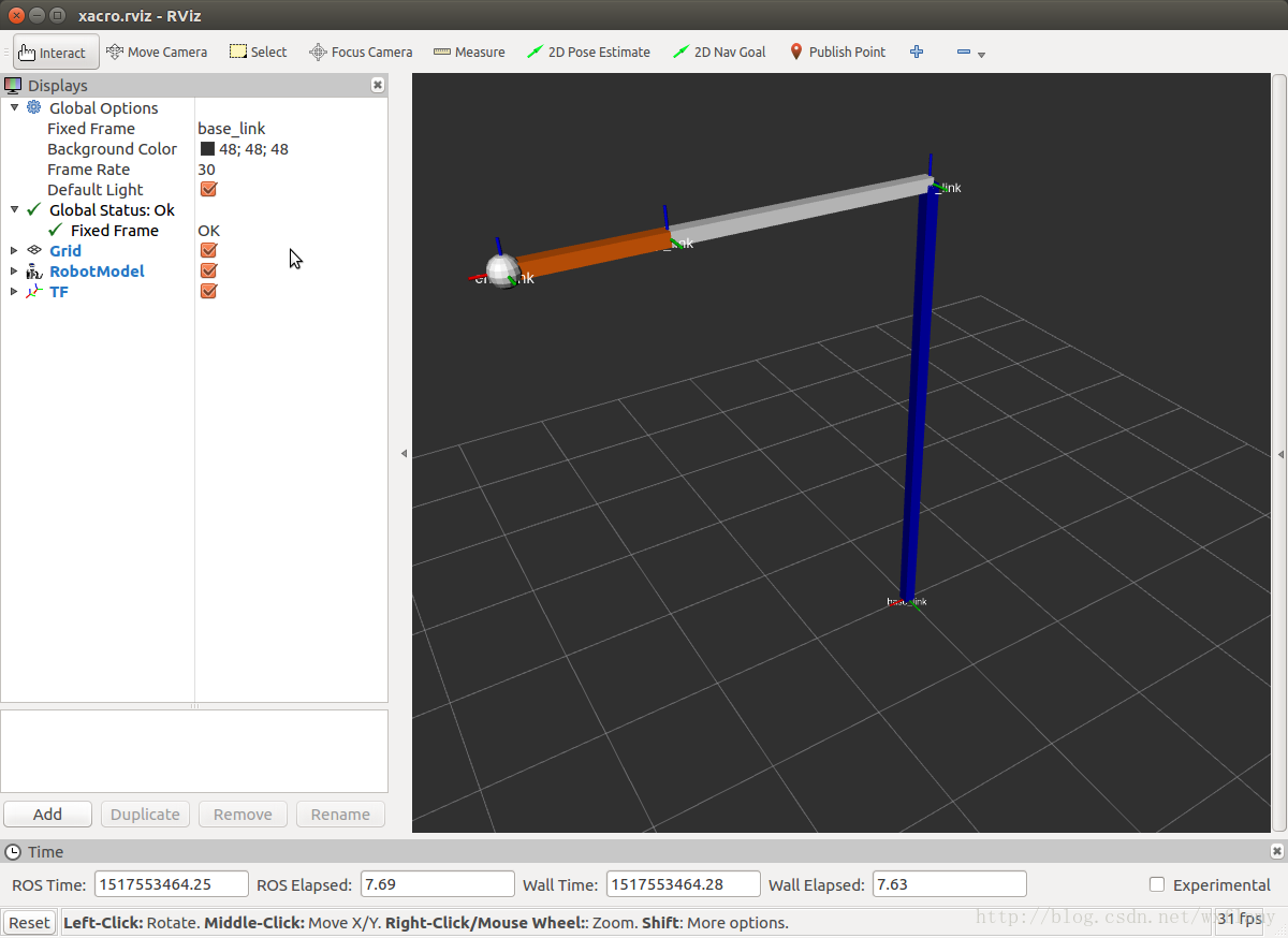
</launch>运行
roslaunch myurdf display_xacro.launch可以观察到跟上面一样的界面,这时改变连杆长度只需要在定义常数的地方修改即可。改变长度后的各个连杆如下
在gazebo中使用URDF模型
怎样在gazebo中启动并且控制我们的机器人呢
先写一个在gazebo中启动的launch文件gazebo.launch
<launch>

  <!-- these are the arguments you can pass this launch file, for example paused:=true -->
  <arg name="paused" default="false"/>
  <arg name="use_sim_time" default="true"/>
  <arg name="gui" default="true"/>
  <arg name="headless" default="false"/>
  <arg name="debug" default="false"/>

  <!-- We resume the logic in empty_world.launch, changing only the name of the world to be launched -->
  <include file="$(find gazebo_ros)/launch/empty_world.launch">
    <!--arg name="world_name" value="$(find myurdf)/robot/robot.world"/-->
    <arg name="debug" value="$(arg debug)" />
    <arg name="gui" value="$(arg gui)" />
    <arg name="paused" value="$(arg paused)"/>
    <arg name="use_sim_time" value="$(arg use_sim_time)"/>
    <arg name="headless" value="$(arg headless)"/>
  </include>

  <!-- Load the URDF into the ROS Parameter Server -->
  <param name="robot_description"
    command="$(find xacro)/xacro --inorder '$(find myurdf)/robot/myfirstrobot.xacro'" />

  <!-- Run a python script to the send a service call to gazebo_ros to spawn a URDF robot -->
  <node name="urdf_spawner" pkg="gazebo_ros" type="spawn_model" respawn="false" output="screen"
    args="-urdf -model myfirstrobot -param robot_description"/>

  <node pkg="robot_state_publisher" type="robot_state_publisher"  name="robot_state_publisher">
    <param name="publish_frequency" type="double" value="30.0" />
    </node>

</launch>运行roslaunch myurdf gazebo.launch是下面的这样。

这是啥玩意儿,我不认识啊。
然后一顿修改啊
<?xml version="1.0"?>
<robot name="myfirstrobot" xmlns:xacro="http://www.ros.org/wiki/xacro">

  <!-- Constants for robot dimensions -->
  <xacro:property name="PI" value="3.1415926535897931"/>
  <xacro:property name="mass" value="1" /> <!-- arbitrary value for mass -->
  <xacro:property name="width" value="0.1" /> <!-- Square dimensions (widthxwidth) of beams -->
  <xacro:property name="height1" value="4" /> <!-- Link 1 -->
  <xacro:property name="height2" value="2" /> <!-- Link 2 -->
  <xacro:property name="height3" value="1" /> <!-- Link 3 -->

  <!-- ros_control plugin -->
    <gazebo>
        <plugin name="gazebo_ros_control" filename="libgazebo_ros_control.so">
            <robotNamespace>/myfirstrobot</robotNamespace>
      <robotSimType>gazebo_ros_control/DefaultRobotHWSim</robotSimType>
        </plugin>
    </gazebo>

  <!-- Link1 -->
  <gazebo reference="base_link">
    <material>Gazebo/Orange</material>
  </gazebo>

  <!-- Link2 -->
  <gazebo reference="middle_link">
    <mu1>0.2</mu1>
    <mu2>0.2</mu2>
    <material>Gazebo/Blue</material>
  </gazebo>

  <!-- Link3 -->
  <gazebo reference="top_link">
    <mu1>0.2</mu1>
    <mu2>0.2</mu2>
    <material>Gazebo/Orange</material>
  </gazebo>

    <!-- Import Rviz colors -->
  <xacro:include filename="$(find myurdf)/robot/materials.xacro" />

  <!-- Used for fixing robot to Gazebo 'base_link' -->
  <link name="world"/>

  <joint name="fixed" type="fixed">
    <parent link="world"/>
    <child link="base_link"/>
  </joint>

    <!-- Base Link -->
    <link name="base_link">
        <visual>
            <geometry>
                <box size="${width} ${width} ${height1}"/>
            </geometry>
            <origin rpy="0 0 0" xyz="0 0 ${height1/2}"/>
            <material name="blue"/>
        </visual>
        <collision>
            <geometry>
                <cylinder length="${height1}" radius="${width+0.1}"/>
            </geometry>
            <origin rpy="0 0 0" xyz="0 0 ${height1/2}"/>
        </collision>
        <inertial>
      <origin xyz="0 0 ${height1/2}" rpy="0 0 0"/>
      <mass value="${mass}"/>
      <inertia
                ixx="${mass / 12.0 * (width*width + height1*height1)}" ixy="0.0" ixz="0.0"
            iyy="${mass / 12.0 * (height1*height1 + width*width)}" iyz="0.0"
            izz="${mass / 12.0 * (width*width + width*width)}"/>
        </inertial>
    </link>

    <joint name="joint1" type="continuous">
        <parent link="base_link"/>
        <child link="middle_link"/>
        <origin rpy="0 0 0" xyz="0 0 ${height1}"/>
        <axis xyz="0 1 0"/>
    </joint>

    <link name="middle_link">
        <visual>
            <geometry>
                <box size="${width} ${width} ${height2}"/>
            </geometry>
            <origin rpy="0 ${PI/2} 0" xyz="${height2/2} 0 0"/>
            <material name="white"/>
        </visual>
        <collision>
            <geometry>
                <cylinder length="${height2}" radius="${width+0.1}"/>
            </geometry>
            <origin rpy="0 ${PI/2} 0" xyz="${height2/2} 0 0"/>
        </collision>
        <inertial>
      <origin xyz="${height2/2} 0 0" rpy="0 0 0"/>
      <mass value="${mass}"/>
      <inertia
                ixx="${mass / 12.0 * (width*width + width*width)}" ixy="0.0" ixz="0.0"
            iyy="${mass / 12.0 * (height2*height2 + width*width)}" iyz="0.0"
            izz="${mass / 12.0 * (width*width + height2*height2)}"/>
        </inertial>
    </link>

    <joint name="joint2" type="continuous">
        <parent link="middle_link"/>
        <child link="top_link"/>
        <origin rpy="0 0 0" xyz="${height2} 0 0"/>
        <axis xyz="0 1 0"/>
    </joint>

    <link name="top_link">
        <visual>
            <geometry>
                <box size="${width} ${width} ${height3}"/>
            </geometry>
            <origin rpy="0 ${PI/2} 0" xyz="${height3/2} 0 0"/>
            <material name="orange"/>
        </visual>
        <collision>
            <geometry>
                <cylinder length="${height3}" radius="${width+0.1}"/>
            </geometry>
            <origin rpy="0 ${PI/2} 0" xyz="${height3/2} 0 0"/>
        </collision>
        <inertial>
      <origin xyz="${height3/2} 0 0" rpy="0 0 0"/>
      <mass value="${mass}"/>
      <inertia
                ixx="${mass / 12.0 * (width*width + width*width)}" ixy="0.0" ixz="0.0"
            iyy="${mass / 12.0 * (height3*height3 + width*width)}" iyz="0.0"
            izz="${mass / 12.0 * (width*width + height3*height3)}"/>
        </inertial>
    </link>

    <joint name="end" type="revolute">
        <axis xyz="1 0 0"/>
        <limit effort="1000.0" lower="0.0" upper="0.548" velocity="0.5"/>
        <parent link="top_link"/>
        <child link="end_link"/>
        <origin rpy="0 0 0" xyz="${height3} 0 0"/>
    </joint>

    <link name="end_link">
        <visual>
            <geometry>
                <sphere radius="${width}"/>
            </geometry>
            <material name="white"/>
        </visual>
        <collision>
            <geometry>
                <sphere radius="${width+0.05}"/>
            </geometry>
        </collision>
        <inertial>
      <origin xyz="0 0 0" rpy="0 0 0"/>
      <mass value="${mass}"/>
      <inertia
                ixx="${mass / 12.0 * (width*width + width*width)}" ixy="0.0" ixz="0.0"
            iyy="${mass / 12.0 * (width*width + width*width)}" iyz="0.0"
            izz="${mass / 12.0 * (width*width + width*width)}"/>
        </inertial>
    </link>

  <transmission name="tran1">
    <type>transmission_interface/SimpleTransmission</type>
    <joint name="joint1">
      <hardwareInterface>hardware_interface/EffortJointInterface</hardwareInterface>
    </joint>
    <actuator name="motor1">
      <hardwareInterface>hardware_interface/EffortJointInterface</hardwareInterface>
      <mechanicalReduction>1</mechanicalReduction>
    </actuator>
  </transmission>

  <transmission name="tran2">
    <type>transmission_interface/SimpleTransmission</type>
    <joint name="joint2">
      <hardwareInterface>hardware_interface/EffortJointInterface</hardwareInterface>
    </joint>
    <actuator name="motor2">
      <hardwareInterface>hardware_interface/EffortJointInterface</hardwareInterface>
      <mechanicalReduction>1</mechanicalReduction>
    </actuator>
  </transmission>
</robot>
然后这样我认识了
自由摆动,不行吧,能不能加点控制。
答案是能
这篇写的有点长,准备加在ros_control里


评论(0)
您还未登录,请登录后发表或查看评论