

如何在ROS 2中使用URDF创建仿真移动机器人(一)
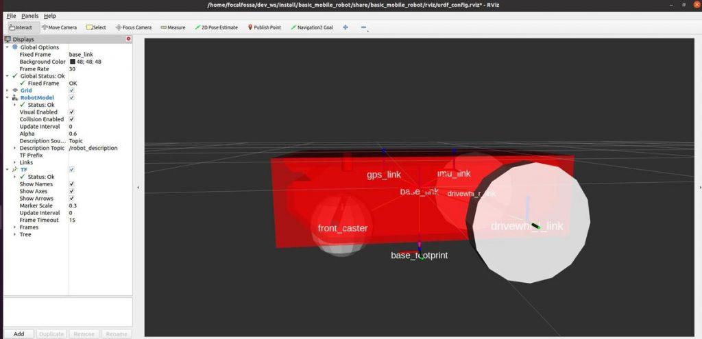
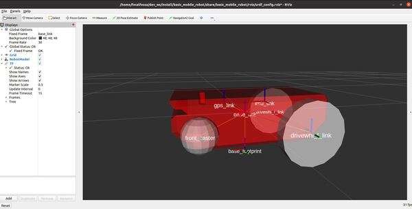
在本教程中,将学习如何使用用于机器人建模的标准 ROS 格式—统一机器人描述格式(URDF)创建仿真的移动机器人。本教程是原文作者 ROS 2导航堆栈(也称为 Nav2)终极指南中的第一个教程。您将创建的仿真机器人看起来应该如下图所示:
机器人专家喜欢在实际建造机器人之前先对其进行仿真以测试不同的算法。您可以想象到物理机器人犯错的代价会很高(例如,移动机器人高速撞到墙上意味着金钱的损失)。
本项目的完整代码可以在此处获得。
现在让我们开始吧!
目录
一、前提条件
二、URDF是什么
三、安装ROS2 Navigation Stack(Nav2)
四、安装重要的ROS 2软件包
五、创建一个ROS 2软件包
六、创建其它目录
七、创建URDF文件
八、添加依赖项
九、创建启动文件
十、添加RViz配置文件
十一、编译构建软件包
十二、在RViz中启动机器人
十三、查看坐标系
一、前提条件
·已在Ubuntu Linux 20.04操作系统中安装好ROS 2 Foxy Fitzroy
·如果使用的是ROS 2的其它发行版,则需要在本教程中提到“foxy”的任何地方将“foxy”替换为您的发行版名称(例如“galactic”)。
·强烈建议您获取最新版本的 ROS 2。如果您使用的是较新版本的 ROS 2,仍然可以按照本教程中的所有步骤进行操作。一切都能正常工作的。
·您已经创建好了一个ROS 2工作空间。在本教程中该工作空间的名称为“dev_ws”,代表“开发工作空间”。
二、URDF是什么
统一机器人描述格式URDF(Universal Robot Description Format)文件是一种XML文件,用于描述机器人在现实世界中的模样。URDF包含机器人的完整物理描述。构建机器人的身体是开始使用 Nav2 的第一步。
机器人的身体由以下两种部件组成:
· 链接
· 关节
链接是机器人的刚性部件。它们是机器人的“骨骼”。
各个链接通过关节相互连接。关节是机器人的移动部分,可以在相互连接的链接之间进行运动。
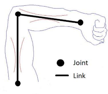
以如下所示的人类手臂为例来思考一下。肩、肘、手腕都是关节。 而上臂、前臂和手掌则都是链接。
对于机械臂,链接和关节应该看起来像下图所示:
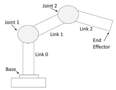
可以看出机械臂由刚性部件(链接)和非刚性部件(关节)组成。 关节处的伺服电机(Servo motors)使得机械臂的链接可以移动。
对于具有激光雷达的移动机器人,其链接和关节应如下图所示:
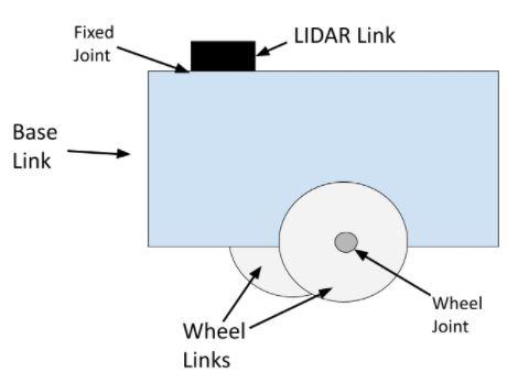
车轮关节是旋转关节。旋转关节可以引起旋转运动。上图中的车轮关节将车轮链接连接到底座(底盘或车架)链接上。
固定关节完全不能运动。从上图中可以看到激光雷达LIDAR通过一个固定关节连接到机器人的底座上(即该关节可以是将LIDAR连接到机器人底座上的一枚简单螺丝钉)。
另外还有棱柱关节。这篇文章中的SCARA机器人就具有一个棱柱关节。棱柱关节可以导致链接之间的线性运动(与旋转运动相对)。
三、安装ROS2 Navigation Stack(Nav2)
现在您知道URDF文件是什么了,让我们开始工作吧。
现在,希望您先完成这个教程以安装ROS 2导航堆栈。一旦完成该教程,就请返回本教程。
别担心,设置ROS 2导航堆栈(Navigation Stack)不需要很长时间。在返回这里之前,请务必完成该教程的全部内容。
四、安装重要的ROS 2软件包
现在需要安装一些将在本教程中使用的重要ROS 2软件包。打开一个新的终端窗口,然后逐个键入以下命令:
sudo apt install ros-foxy-joint-state-publisher-gui
sudo apt install ros-foxy-xacro
上述命令的格式为:
sudo apt install ros-<ros2-distro>-joint-state-publisher-gui
sudo apt install ros-<ros2-distro>-xacro
您需要将 <ros2-distro> 替换为您正在使用的 ROS 2 发行版。在本示例下,原文作者使用的是 ROS 2 Foxy Fitzroy,简称“foxy”。
五、创建一个ROS 2软件包
现在让我们在工作空间中创建一个ROS 2软件包。
在一个新的终端窗口中,进入到您工作空间存放源代码的src目录:
cd ~/dev_ws/src现在使用以下命令来创建软件包:
ros2 pkg create --build-type ament_cmake basic_mobile_robot六、创建其它目录
进入到该软件包目录中:
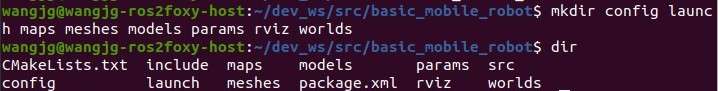
cd ~/dev_ws/src/basic_mobile_robot使用以下命令来创建一些其它目录:
mkdir config launch maps meshes models params rviz worlds键入以下命令以确认这些目录创建成功:
dir结果应该如下图所示:
现在通过键入以下命令来构建该软件包:
cd ~/dev_ws
colcon build
让我们在 bashrc 文件中添加下面这样一行脚本,以使我们能够使用以下命令在终端窗口中从任何当前目录移至该软件包所在目录:
colcon_cd basic_mobile_robot其中“cd”表示“更改目录”。
请注意,在ROS 1中需要键入roscd命令来更改目录。而在ROS 2中,则要使用colcon_cd命令。
打开一个终端窗口,并逐个键入以下命令:
echo "source /usr/share/colcon_cd/function/colcon_cd.sh" >> ~/.bashrc
echo "export _colcon_cd_root=~/dev_ws" >> ~/.bashrc
现在打开一个新的终端窗口。要直接进入到basic_mobile_robot这个ROS 2软件包目录,请键入命令:
colcon_cd basic_mobile_robot上面这个命令会让你直接从Linux系统的任何目录中直接进入到 basic_mobile_robot 软件包所在目录。该命令格式为:
colcon_cd [ROS 2 package name]七、创建URDF文件
在本节中将会逐步构建该移动机器人。该机器人将会用一种表示机器人模型的 XML 文件即统一机器人描述格式(URDF)定义。
打开一个新的终端窗口,并键入以下命令:
colcon_cd basic_mobile_robot
cd models请确保您已经安装好了Gedit文本编辑器软件:
sudo apt-get install gedit创建一个名为basic_mobile_bot_v1.urdf的新文件:
gedit basic_mobile_bot_v1.urdf在这个文件中,我们会定义机器人的外观(即视觉属性)、机器人在碰撞到物体时的行为(即碰撞属性)及其质量(即惯性属性)。
在该URDF文件中输入下面这段代码:
<?xml version="1.0" ?>
<robot name="basic_mobile_bot" xmlns:xacro="http://ros.org/wiki/xacro">

  <!-- ****************** ROBOT CONSTANTS *******************************  -->
  <!-- Define the size of the robot's main chassis in meters -->
  <xacro:property name="base_width" value="0.39"/>
  <xacro:property name="base_length" value="0.70"/>
  <xacro:property name="base_height" value="0.20"/>

  <!-- Define the shape of the robot's two back wheels in meters -->
  <xacro:property name="wheel_radius" value="0.14"/>
  <xacro:property name="wheel_width" value="0.06"/>

  <!-- x-axis points forward, y-axis points to left, z-axis points upwards -->
  <!-- Define the gap between the wheel and chassis along y-axis in meters -->
  <xacro:property name="wheel_ygap" value="0.035"/>

  <!-- Position the wheels along the z-axis -->
  <xacro:property name="wheel_zoff" value="0.05"/>

  <!-- Position the wheels along the x-axis -->
  <xacro:property name="wheel_xoff" value="0.221"/>

  <!-- Position the caster wheel along the x-axis -->
  <xacro:property name="caster_xoff" value="0.217"/>

  <!-- Define intertial property macros  -->
  <xacro:macro name="box_inertia" params="m w h d">
    <inertial>
      <origin xyz="0 0 0" rpy="${pi/2} 0 ${pi/2}"/>
      <mass value="${m}"/>
      <inertia ixx="${(m/12) * (h*h + d*d)}" ixy="0.0" ixz="0.0" iyy="${(m/12) * (w*w + d*d)}" iyz="0.0" izz="${(m/12) * (w*w + h*h)}"/>
    </inertial>
  </xacro:macro>

  <xacro:macro name="cylinder_inertia" params="m r h">
    <inertial>
      <origin xyz="0 0 0" rpy="${pi/2} 0 0" />
      <mass value="${m}"/>
      <inertia ixx="${(m/12) * (3*r*r + h*h)}" ixy = "0" ixz = "0" iyy="${(m/12) * (3*r*r + h*h)}" iyz = "0" izz="${(m/2) * (r*r)}"/>
    </inertial>
  </xacro:macro>

  <xacro:macro name="sphere_inertia" params="m r">
    <inertial>
      <mass value="${m}"/>
      <inertia ixx="${(2/5) * m * (r*r)}" ixy="0.0" ixz="0.0" iyy="${(2/5) * m * (r*r)}" iyz="0.0" izz="${(2/5) * m * (r*r)}"/>
    </inertial>
  </xacro:macro>

  <!-- ****************** ROBOT BASE FOOTPRINT ***************************  -->
  <!-- Define the center of the main robot chassis projected on the ground -->
  <link name="base_footprint"/>

  <!-- The base footprint of the robot is located underneath the chassis -->
  <joint name="base_joint" type="fixed">
    <parent link="base_footprint"/>
    <child link="base_link" />
    <origin xyz="0.0 0.0 ${(wheel_radius+wheel_zoff)}" rpy="0 0 0"/>
  </joint>

  <!-- ********************** ROBOT BASE *********************************  -->
  <link name="base_link">
    <visual>
      <origin xyz="0 0 -0.05" rpy="1.5707963267949 0 3.141592654"/>
      <geometry>
        <mesh filename="package://basic_mobile_robot/meshes/robot_base.stl" />
      </geometry>
      <material name="Red">
        <color rgba="${255/255} ${0/255} ${0/255} 1.0"/>
      </material>
    </visual>

    <collision>
      <geometry>
        <box size="${base_length} ${base_width} ${base_height}"/>
      </geometry>
    </collision>

    <xacro:box_inertia m="40.0" w="${base_width}" d="${base_length}" h="${base_height}"/>

  </link>

  <gazebo reference="base_link">
    <material>Gazebo/Red</material>
  </gazebo>

  <!-- *********************** DRIVE WHEELS ******************************  -->

  <xacro:macro name="wheel" params="prefix x_reflect y_reflect">
    <link name="${prefix}_link">
      <visual>
        <origin xyz="0 0 0" rpy="1.5707963267949 0 0"/>
        <geometry>
            <cylinder radius="${wheel_radius}" length="${wheel_width}"/>
        </geometry>
        <material name="White">
          <color rgba="${255/255} ${255/255} ${255/255} 1.0"/>
        </material>
      </visual>

      <collision>
        <origin xyz="0 0 0" rpy="${pi/2} 0 0"/>
        <geometry>
          <cylinder radius="${wheel_radius}" length="${wheel_width}"/>
        </geometry>
      </collision>

      <xacro:cylinder_inertia m="110.5" r="${wheel_radius}" h="${wheel_width}"/>

    </link>

    <!-- Connect the wheels to the base_link at the appropriate location, and
         define a continuous joint to allow the wheels to freely rotate about
         an axis -->
    <joint name="${prefix}_joint" type="revolute">
      <parent link="base_link"/>
      <child link="${prefix}_link"/>
      <origin xyz="${x_reflect*wheel_xoff} ${y_reflect*(base_width/2+wheel_ygap)} ${-wheel_zoff}" rpy="0 0 0"/>
      <limit upper="3.1415" lower="-3.1415" effort="30" velocity="5.0"/>
      <axis xyz="0 1 0"/>
    </joint>
  </xacro:macro>

  <!-- Instantiate two wheels using the macro we just made through the
       xacro:wheel tags. We also define the parameters to have one wheel
       on both sides at the back of our robot (i.e. x_reflect=-1). -->
  <xacro:wheel prefix="drivewhl_l" x_reflect="-1" y_reflect="1" />
  <xacro:wheel prefix="drivewhl_r" x_reflect="-1" y_reflect="-1" />

  <!-- *********************** CASTER WHEEL ******************************  -->
  <!-- We add a caster wheel. It will be modeled as sphere.
       We define the wheel’s geometry, material and the joint to connect it to
       base_link at the appropriate location. -->
  <link name="front_caster">
    <visual>
      <geometry>
        <sphere radius="${(wheel_radius+wheel_zoff-(base_height/2))}"/>
      </geometry>
      <material name="White">
        <color rgba="${255/255} ${255/255} ${255/255} 1.0"/>
      </material>
    </visual>
    <collision>
      <origin xyz="0 0 0" rpy="0 0 0"/>
      <geometry>
        <sphere radius="${(wheel_radius+wheel_zoff-(base_height/2))}"/>
      </geometry>
    </collision>
    <xacro:sphere_inertia m="10.05" r="${(wheel_radius+wheel_zoff-(base_height/2))}"/>
  </link>

  <gazebo reference="front_caster">
    <mu1>0.01</mu1>
    <mu2>0.01</mu2>
    <material>Gazebo/White</material>
  </gazebo>

  <joint name="caster_joint" type="fixed">
    <parent link="base_link"/>
    <child link="front_caster"/>
    <origin xyz="${caster_xoff} 0.0 ${-(base_height/2)}" rpy="0 0 0"/>
  </joint>

  <!-- *********************** IMU SETUP *********************************  -->
  <!-- Each sensor must be attached to a link.                              -->

  <joint name="imu_joint" type="fixed">
    <parent link="base_link"/>
    <child link="imu_link"/>
    <origin xyz="-0.10 0 0.05" rpy="0 0 0"/>
  </joint>

  <link name="imu_link"/>

  <!-- *********************** GPS SETUP **********************************  -->
  <joint name="gps_joint" type="fixed">
    <parent link="base_link"/>
    <child link="gps_link"/>
    <origin xyz="0.10 0 0.05" rpy="0 0 0"/>
  </joint>

  <link name="gps_link"/>

</robot>
保存并关闭该文件。
所有的机器人都是由链接和关节组成的。如果你浏览一下该URDF文件,你就会看到我们已经定义了我们的两轮机器人的每个链接和每个关节。
移动机器人的链接包括机器人底座(通常称为“底盘”)、两个驱动轮、前脚轮、IMU和GPS。此外还定义了一个称为“底座足迹(base footprint)”的虚拟链接。底座足迹(如这篇文章中所示)是机器人中心正下方的一个链接。
机器人的每个链接都通过一个关节进行连接。唯一移动的两个关节是左右两个车轮的旋转关节,这两个关节的旋转会导致车轮链接转动。
在这个URDF文件中使用了xacro(即 XML 宏语言)。Xacro 使我们能够定义可以在整个URDF文件中重用的字符串常量(例如“wheel_radius”),从而帮助避免URDF文件中的混乱。
要了解有关URDF文件的更多信息,请查看其官方文档。
现在进入到meshes目录:
cd ~/dev_ws/src/basic_mobile_robot/meshes将这些STL文件添加到您的meshes目录中。网格是一种可以让您的机器人看起来更加逼真(而不仅仅是使用基本形状,如方盒和球体)的文件。
除了使用本教程提供的STL文件之外,您也可以使用SolidWorks之类的程序生成您自己的STL文件。您还可以使用名为 Blender 的程序来创建DAE文件。URDF支持STL和DAE格式的网格。
(待续)
*英语原文地址:https://automaticaddison.com/ho


评论(1)
您还未登录,请登录后发表或查看评论