

该机器人开发板的用法和介绍以本文章为准。
最新的代码github仓库为准:https://github.com/Allen953/Baize_ServoDriver_esp32
介绍
仓库总是存放最新代码,CSDN的代码可能存在滞后 !
出于制作机器人的需要,设计了这块儿32路舵机驱动板,板子可以驱动从5~12V的pwm舵机,适应电压范围较宽,所以用起来会非常方便。
板载有电压监测电路和蜂鸣器,这样如果你使用电池为机器人供电时,可以通过电压检测电路来测量电池电量情况,如果电量过低,则需要报警并停止机器人动作,提示我们进行充电。
板载还有mpu6050,这样我们可以感知机器人的姿态等信息,可以根据机器人姿态进行动作的规划。
同时板载一个小型彩色屏幕1.14寸,140*240的分辨率,可以实时显示板子和机器人的状态,方便机器人的现场测试。
板子上还有几个独立按键,作为调试按钮,可以灵活定制按钮功能,对机器人进行调试。
硬件原理图及PCB文件和资料开源链接:GitHub - Allen953/Baize_ServoDriver_esp32
如果你的Arduino IDE由于配置问题无法正确编译仓库代码,可以直接烧录仓库里代码文件旁边的固件(bin文件)来对板子进行测试,效果是一样的,只是省去了用Arduino IDE编译代码这个过程。
具体的烧录固件的方法见此教程:https://blog.csdn.net/qqliuzhitong/article/details/125852218
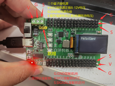
接线说明
两排排针用于接32路舵机用,舵机线由S,V,G构成,注意正反。
蓝色接线端子用于接电源,如果用电池直供板子,则调帽调到左边,用于检测默认电池输入电压。如果电池经过压降模块之后,给板子供电,则板子检测到的电压为板子本身的电压,无法反映电池真实电压,这时,将电池正极接入绿色接线端子的S端子里面,同时将跳帽移到右边,这时板子电压检测绿色端子S端输入的电压,即电池电压。
电压过低,则启动蜂鸣器报警同时停止程序运行。
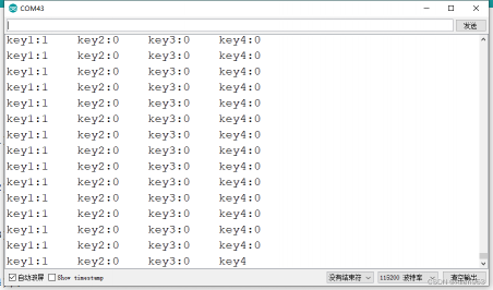
例程1:按键检测
/*******************************************************
   Baize_ServoDriver_esp32
   功能:测试独立按键
   引脚:key1:35    key2:34    key3:39    key4:36
   Designer: Allen
   E-mail:953598974@qq.com
   Date:2022-09-09 21:08
*******************************************************/

#define key1 35
#define key2 34
#define key3 39
#define key4 36

void setup() {
  Serial.begin(115200);
  pinMode(key1,INPUT);
  pinMode(key2,INPUT);
  pinMode(key3,INPUT);
  pinMode(key4,INPUT);
}

void loop() {
  Serial.print("key1:");
  Serial.print(digitalRead(key1));
  Serial.print("    ");
  Serial.print("key2:");
  Serial.print(digitalRead(key2));
  Serial.print("    ");
  Serial.print("key3:");
  Serial.print(digitalRead(key3));
  Serial.print("    ");
  Serial.print("key4:");
  Serial.print(digitalRead(key4));
  Serial.println();
}
当我们按下某个按键之后,打开串口,我们会发现这个按键从0变为了1,即从低电平变为高电平。
例程2:发现(校验)板子上的iic设备
/*******************************************************
   Baize_ServoDriver_esp32
   功能:扫描iic设备
   引脚:SDA:21   SCL:22
   Designer: Allen
   E-mail:953598974@qq.com
   Date:2022-08-22
 *******************************************************/
#include <Wire.h>

void setup()
{
  Wire.begin();
  Serial.begin(115200);
}

void loop()
{
  byte error, address;
  int nDevices;
  Serial.println("Scanning...");

  nDevices = 0;
  for(address = 1; address < 127; address++ )
  {
    Wire.beginTransmission(address);
    error = Wire.endTransmission();

    if (error == 0)
    {
      Serial.print("I2C device found at address 0x");
      if (address<16)
        Serial.print("0");
      Serial.print(address,HEX);
      Serial.println("  !");

      nDevices++;
    }
    else if (error==4)
    {
      Serial.print("Unknown error at address 0x");
      if (address<16)
        Serial.print("0");
      Serial.println(address,HEX);
    }
  }
  if (nDevices == 0)
    Serial.println("No I2C devices found\n");
  else
    Serial.println("done\n");
  delay(5000);
}
例程3:控制32路舵机匀速旋转从0-180度,再从180-0度
/*******************************************************
   Baize_ServoDriver_esp32
   功能:测试舵机
   引脚:SDA:21   SCL:22
   对于ARDUINO UNO,SCL:A5,SDA:A4
   Designer: Allen
   E-mail:953598974@qq.com
   Date:2022-08-22
*******************************************************/

#include <Wire.h>
#include <Adafruit_PWMServoDriver.h>

Adafruit_PWMServoDriver pwm = Adafruit_PWMServoDriver();
Adafruit_PWMServoDriver pwm1 = Adafruit_PWMServoDriver(0x41);

//#define SERVOMIN  102               //0.5/20 * 4096 = 102
//#define SERVOMID  307               //1.5/20 * 4096 = 307
//#define SERVOMAX  512               //2.5/20 * 4096 = 512

//实际测试
#define SERVOMIN  102
#define SERVOMID  327
#define SERVOMAX  552

void setup() {
  Serial.begin(115200);
  Serial.println("16 channel Servo test!");

  pwm.begin();
  pwm1.begin();
  pwm.setPWMFreq(50);  // Analog servos run at ~50 Hz updates
  pwm1.setPWMFreq(50);  // Analog servos run at ~50 Hz updates
}

void loop() {
   for (uint16_t pulselen = SERVOMIN; pulselen < SERVOMAX; pulselen++) {
        for(int i=0;i<16;i++)
        {
          pwm.setPWM(i, 0, pulselen);
          pwm1.setPWM(i, 0, pulselen);
        }
        delayMicroseconds(200);
   }
   for (uint16_t pulselen = SERVOMAX; pulselen > SERVOMIN; pulselen--) {
        for(int i=0;i<16;i++)
        {
          pwm.setPWM(i, 0, pulselen);
          pwm1.setPWM(i, 0, pulselen);
        }
        delayMicroseconds(200);
   }
}
例程4:控制32路舵机从0,90,180,90,0度之间循环。
/*******************************************************
   Baize_ServoDriver_esp32
   功能:测试舵机
   引脚:SDA:21   SCL:22
   对于ARDUINO UNO,SCL:A5,SDA:A4
   Designer: Allen
   E-mail:953598974@qq.com
   Date:2022-08-22
*******************************************************/

#include <Wire.h>
#include <Adafruit_PWMServoDriver.h>

Adafruit_PWMServoDriver pwm = Adafruit_PWMServoDriver();
Adafruit_PWMServoDriver pwm1 = Adafruit_PWMServoDriver(0x41);

#define SERVOMIN  102               //0.5/20 * 4096 = 102
#define SERVOMID  307              //(102+512)/2=307
#define SERVOMAX  512               //2.5/20 * 4096 = 512

//pwm.setPWM(i, 0, pulse);i=0~15对应第0-15个舵机;pwm1.setPWM(j, 0, pulse);j=0~15对应第16-31个舵机,

void setup() {
  Serial.begin(115200);
  Serial.println("16 channel Servo test!");

  pwm.begin();
  pwm1.begin();
  pwm.setPWMFreq(50);  // Analog servos run at ~50 Hz updates
  pwm1.setPWMFreq(50);  // Analog servos run at ~50 Hz updates
}

void loop() {
   //全部舵机转到0度
        for(int i=0;i<16;i++)
        {
          pwm.setPWM(i, 0, SERVOMIN);
          pwm1.setPWM(i, 0, SERVOMIN);
        }
        delayMicroseconds(200);
        delay(1000);
  //全部舵机转到90度
        for(int i=0;i<16;i++)
        {
          pwm.setPWM(i, 0, SERVOMID);
          pwm1.setPWM(i, 0, SERVOMID);
        }
        delayMicroseconds(200);
        delay(1000);
  //全部舵机转到180度
        for(int i=0;i<16;i++)
        {
          pwm.setPWM(i, 0, SERVOMAX);
          pwm1.setPWM(i, 0, SERVOMAX);
        }
        delayMicroseconds(200);
        delay(1000);
  //全部舵机转到90度
        for(int i=0;i<16;i++)
        {
          pwm.setPWM(i, 0, SERVOMID);
          pwm1.setPWM(i, 0, SERVOMID);
        }
        delayMicroseconds(200);
        delay(1000);
}
例程5:控制32路舵机从0-180度之间循环,正弦速度。
/*******************************************************
   Baize_ServoDriver_esp32
   功能:测试舵机
   引脚:SDA:21   SCL:22
   对于ARDUINO UNO,SCL:A5,SDA:A4
   Designer: Allen
   E-mail:953598974@qq.com
   Date:2022-11-13 15:47
*******************************************************/

#include <Wire.h>
#include <Adafruit_PWMServoDriver.h>

#define pi 3.1415926
#define pi2 1.5707963
#define radtodeg 57.295780
//position = -pi/2 * cos((pi/2) * t) + pi/2
//velocity = (pi^2)/4 * sin((pi/2) * t)

Adafruit_PWMServoDriver pwm = Adafruit_PWMServoDriver();
Adafruit_PWMServoDriver pwm1 = Adafruit_PWMServoDriver(0x41);

//#define SERVOMIN  102               //0.5/20 * 4096 = 102
//#define SERVOMID  307               //1.5/20 * 4096 = 307
//#define SERVOMAX  512               //2.5/20 * 4096 = 512
//实际测试
#define SERVOMIN  102
#define SERVOMID  327
#define SERVOMAX  552

long time_p = 0;

void setup() {
  // put your setup code here, to run once:
  Serial.begin(115200);

  pwm.begin();
  pwm1.begin();
  pwm.setPWMFreq(50);  // Analog servos run at ~50 Hz updates
  pwm1.setPWMFreq(50);  // Analog servos run at ~50 Hz updates
}

void loop() {
  // put your main code here, to run repeatedly:
  float t = float(millis())/1000.0;
  float v = (pi*pi)/4 * sin((pi2) * t);
  float p = -pi2 * cos((pi2) * t) + pi2;

  int pulselen = int(map(p * radtodeg,0.0,180.0,float(SERVOMIN),float(SERVOMAX)));

  for(int i=0;i<16;i++)
  {
    pwm.setPWM(i, 0, pulselen);
    pwm1.setPWM(i, 0, pulselen);
  }
  Serial.println(pulselen);
  delay(10);
}
例程6:测试MPU6050
/*******************************************************
   Baize_ServoDriver_esp32
   功能:测试mpu6050
   引脚:SDA:21   SCL:22
   对于ARDUINO UNO,SCL:A5,SDA:A4
   Designer: Allen
   E-mail:953598974@qq.com
   Date:2022-08-22
*******************************************************/

#include "Wire.h"          //I2C通讯库
#include "I2Cdev.h"        //
#include "MPU6050.h"       //mpu6050库

MPU6050 mympu;             //定义mympu对象

float pi=3.1415926;             //Π的值,用于单位转换
float AcceRatio=16384.0;        //加速度计比例系数
float GyroRatio=131.0;          //陀螺仪比例系数
//定义3个变量,用于存储倾角数据
float angle_x=0.0,angle_y=0.0,angle_z=0.0;
int16_t ax=0,ay=0,az=0,gx=0,gy=0,gz=0;     //加速度计陀螺仪原始数据
float accx=0.0,accy=0.0,accz=0.0;

void setup(){
  Wire.begin();//开启iic通讯,mpu6050的数据传输协议为iic
  Serial.begin(115200);//打开串口
  mympu.initialize();  //初始化mpu6050
}

void loop() {
    //通过调用该函数,一次性从mpu6050获取6轴数据
    mympu.getMotion6(&ax,&ay,&az,&gx,&gy,&gz);
    accx=ax/AcceRatio;              //x轴加速度
    accy=ay/AcceRatio;              //y轴加速度
    accz=az/AcceRatio;              //z轴加速度
    angle_x=(atan(accx/accz)*180/pi); //计算身体前后的倾角,绕y轴的转角
    angle_y=(atan(accy/accz)*180/pi); //计算身体左右的倾角,绕x轴的转角
    Serial.print(az);Serial.print("     ");//将z轴加速度原始数据输出
    Serial.print(accx);Serial.print("     ");//将3轴加速度输出(单位:g)
    Serial.print(accy);Serial.print("     ");//将两个转角从串口输出
    Serial.print(accz);Serial.print("     ");//将两个转角从串口输出
    Serial.print(angle_x);Serial.print("     ");//将两个转角从串口输出
    Serial.print(angle_y);Serial.println("   ");
    delay(100);
}
这个例程貌似跑不通,但是烧录mpu6050库里面的dmp例程可以跑通,库里的其他例程好像也跑不通,应该是代码哪里有问题。

/*******************************************************
   Baize_ServoDriver_esp32
   功能:测试MPU6050(DMP例程)
   引脚:MOSI:21   CLK:18   RS:12   RES:13   CS:5   BLK:15
   Designer: Allen
   E-mail:953598974@qq.com
   Date:2022-09-09 21:58
*******************************************************/
#include "I2Cdev.h"

#include "MPU6050_6Axis_MotionApps20.h"

#if I2CDEV_IMPLEMENTATION == I2CDEV_ARDUINO_WIRE
    #include "Wire.h"
#endif

MPU6050 mpu;

#define OUTPUT_READABLE_YAWPITCHROLL

#define INTERRUPT_PIN 2  // use pin 2 on Arduino Uno & most boards
bool blinkState = false;

bool dmpReady = false;  // set true if DMP init was successful
uint8_t mpuIntStatus;   // holds actual interrupt status byte from MPU
uint8_t devStatus;      // return status after each device operation (0 = success, !0 = error)
uint16_t packetSize;    // expected DMP packet size (default is 42 bytes)
uint16_t fifoCount;     // count of all bytes currently in FIFO
uint8_t fifoBuffer[64]; // FIFO storage buffer

// orientation/motion vars
Quaternion q;           // [w, x, y, z]         quaternion container
VectorInt16 aa;         // [x, y, z]            accel sensor measurements
VectorInt16 aaReal;     // [x, y, z]            gravity-free accel sensor measurements
VectorInt16 aaWorld;    // [x, y, z]            world-frame accel sensor measurements
VectorFloat gravity;    // [x, y, z]            gravity vector
float euler[3];         // [psi, theta, phi]    Euler angle container
float ypr[3];           // [yaw, pitch, roll]   yaw/pitch/roll container and gravity vector

// packet structure for InvenSense teapot demo
uint8_t teapotPacket[14] = { '$', 0x02, 0,0, 0,0, 0,0, 0,0, 0x00, 0x00, '\r', '\n' };

volatile bool mpuInterrupt = false;     // indicates whether MPU interrupt pin has gone high
void dmpDataReady() {
    mpuInterrupt = true;
}

void setup() {
    // join I2C bus (I2Cdev library doesn't do this automatically)
    #if I2CDEV_IMPLEMENTATION == I2CDEV_ARDUINO_WIRE
        Wire.begin();
        Wire.setClock(400000); // 400kHz I2C clock. Comment this line if having compilation difficulties
    #elif I2CDEV_IMPLEMENTATION == I2CDEV_BUILTIN_FASTWIRE
        Fastwire::setup(400, true);
    #endif
    // initialize serial communication
    // (115200 chosen because it is required for Teapot Demo output, but it's
    // really up to you depending on your project)
    Serial.begin(115200);
    while (!Serial); // wait for Leonardo enumeration, others continue immediately

    // initialize device
    Serial.println(F("Initializing I2C devices..."));
    mpu.initialize();
    pinMode(INTERRUPT_PIN, INPUT);

    // verify connection
    Serial.println(F("Testing device connections..."));
    Serial.println(mpu.testConnection() ? F("MPU6050 connection successful") : F("MPU6050 connection failed"));

    // wait for ready
    Serial.println(F("\nSend any character to begin DMP programming and demo: "));
    while (Serial.available() && Serial.read()); // empty buffer
    while (!Serial.available());                 // wait for data
    while (Serial.available() && Serial.read()); // empty buffer again

    // load and configure the DMP
    Serial.println(F("Initializing DMP..."));
    devStatus = mpu.dmpInitialize();

    // supply your own gyro offsets here, scaled for min sensitivity
    mpu.setXGyroOffset(220);
    mpu.setYGyroOffset(76);
    mpu.setZGyroOffset(-85);
    mpu.setZAccelOffset(1788); // 1688 factory default for my test chip

    // make sure it worked (returns 0 if so)
    if (devStatus == 0) {
        // Calibration Time: generate offsets and calibrate our MPU6050
        mpu.CalibrateAccel(6);
        mpu.CalibrateGyro(6);
        mpu.PrintActiveOffsets();
        // turn on the DMP, now that it's ready
        Serial.println(F("Enabling DMP..."));
        mpu.setDMPEnabled(true);
        // enable Arduino interrupt detection
        Serial.print(F("Enabling interrupt detection (Arduino external interrupt "));
        Serial.print(digitalPinToInterrupt(INTERRUPT_PIN));
        Serial.println(F(")..."));
        attachInterrupt(digitalPinToInterrupt(INTERRUPT_PIN), dmpDataReady, RISING);
        mpuIntStatus = mpu.getIntStatus();
        // set our DMP Ready flag so the main loop() function knows it's okay to use it
        Serial.println(F("DMP ready! Waiting for first interrupt..."));
        dmpReady = true;

        // get expected DMP packet size for later comparison
        packetSize = mpu.dmpGetFIFOPacketSize();
    } else {
        // ERROR!
        // 1 = initial memory load failed
        // 2 = DMP configuration updates failed
        // (if it's going to break, usually the code will be 1)
        Serial.print(F("DMP Initialization failed (code "));
        Serial.print(devStatus);
        Serial.println(F(")"));
    }
}
void loop() {
    // if programming failed, don't try to do anything
    if (!dmpReady) return;
    if (mpu.dmpGetCurrentFIFOPacket(fifoBuffer)) { // Get the Latest packet
            mpu.dmpGetQuaternion(&q, fifoBuffer);
            mpu.dmpGetGravity(&gravity, &q);
            mpu.dmpGetYawPitchRoll(ypr, &q, &gravity);
            Serial.print("ypr\t");
            Serial.print(ypr[0] * 180/M_PI);
            Serial.print("\t");
            Serial.print(ypr[1] * 180/M_PI);
            Serial.print("\t");
            Serial.println(ypr[2] * 180/M_PI);
    }
}
例程7:测试蜂鸣器
/*******************************************************
   Baize_ServoDriver_esp32
   功能:测试蜂鸣器
   引脚:D2(GPIO2)
   Designer: Allen
   E-mail:953598974@qq.com
   Date:2022-08-22
 *******************************************************/
#define LED_PWM 2 //把调用的GPIO引脚进行了一个宏定义
int freq = 5000;
int ledChannel = 0;
int resolution = 8;
void setup() {
  ledcSetup(ledChannel, freq, resolution);
  ledcAttachPin(LED_PWM, ledChannel);
}
void loop() {
  ledcWrite(ledChannel, 180);
  delay(100);
  ledcWrite(ledChannel, 0);
  delay(100);
}
例程8:带电压监测的板子测试程序
升级版,主控esp32。供电范围5-12V。当我用7.4V的2S锂电池给舵机供电时,用这个程序来进行板子测试,由于测试时间较长,担心电池过放,所以通过电压监测,当电压过低时,将不再驱动舵机工作。
/*******************************************************
   Baize_ServoDriver_esp32
   功能:测试显示屏
   引脚:MOSI:21   CLK:18   RS:12   RES:13   CS:5   BLK:15
   Designer: Allen
   E-mail:953598974@qq.com
   Date:2022-08-22
*******************************************************/

#include <Wire.h>
#include <Adafruit_PWMServoDriver.h>

Adafruit_PWMServoDriver pwm = Adafruit_PWMServoDriver();
Adafruit_PWMServoDriver pwm1 = Adafruit_PWMServoDriver(0x41);

#define SERVOMIN  102               //0.5/20 * 4096 = 102
#define SERVOMAX  512               //2.5/20 * 4096 = 512
//pcb板测试时,如果是2S的锂电池供电,则以此电压为阈值,低于此电压时,不再驱动舵机运动,保护电池。
float voltage_threshold = 6.5;
int voltage_testpin = 26;
float voltage_b = 0.0;

bool servo_f = 1;


void setup() {
  Serial.begin(115200);
  Serial.println();
  Serial.println("16 channel Servo test!");

  pwm.begin();
  pwm1.begin();
  pwm.setPWMFreq(50);  // Analog servos run at ~50 Hz updates
  pwm1.setPWMFreq(50);  // Analog servos run at ~50 Hz updates

  delay(200);
  for(int i=0;i<16;i++)
  {
    pwm.setPWM(i, 0, SERVOMIN); // 驱动32路舵机转到0度
    pwm1.setPWM(i, 0, SERVOMIN);// 驱动32路舵机转到0度
  }
  delay(2000);
  for (uint16_t pulselen = SERVOMIN; pulselen < SERVOMAX; pulselen++) {
        for(int i=0;i<16;i++)
        {
          pwm.setPWM(i, 0, pulselen);
          pwm1.setPWM(i, 0, pulselen);
        }
        delayMicroseconds(200);
  }
}

void loop() {
  if(servo_f==1)
  {
        for (uint16_t pulselen = SERVOMIN; pulselen < SERVOMAX; pulselen++) {
              for(int i=0;i<16;i++)
              {
                pwm.setPWM(i, 0, pulselen);
                pwm1.setPWM(i, 0, pulselen);
              }
              delayMicroseconds(200);
        }
        //电压检测
        int voltage_sum = 0.0;
        for(int i=0;i<10;i++)
        {
          voltage_sum += float(analogRead(voltage_testpin))/4095.0*3.3*4.0;
          Serial.println(analogRead(voltage_testpin));
          delay(100);
        }
        voltage_b = voltage_sum / 10.0;
        Serial.println(voltage_b);
        if(voltage_b<voltage_threshold)
        servo_f = 0;

        for(int i=0;i<16;i++)
        {
          pwm.setPWM(i, 0, SERVOMIN); // 驱动32路舵机转到0度
          pwm1.setPWM(i, 0, SERVOMIN);// 驱动32路舵机转到0度
        }
        delay(2000);
  }


}
例程9:显示屏测试
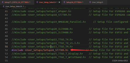
我们还是使用TFT_ESPI库来驱动这块屏幕,首先进行自定义设置:
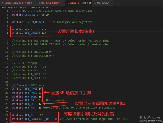
最终Setup24_ST7789.h文件内容如下:
// ST7789 240 x 240 display with no chip select line
#define USER_SETUP_ID 24
#define ST7789_DRIVER // Configure all registers
#define TFT_WIDTH 135
#define TFT_HEIGHT 240
//#define TFT_RGB_ORDER TFT_RGB // Colour order Red-Green-Blue
//#define TFT_RGB_ORDER TFT_BGR // Colour order Blue-Green-Red
//#define TFT_INVERSION_ON
//#define TFT_INVERSION_OFF
// DSTIKE stepup
//#define TFT_DC 23
//#define TFT_RST 32
//#define TFT_MOSI 26
//#define TFT_SCLK 27
// Generic ESP32 setup
#define TFT_MISO 19
#define TFT_MOSI 23
#define TFT_SCLK 18
#define TFT_CS 5 // Not connected
#define TFT_DC 12
#define TFT_RST 13 // Connect reset to ensure display initialises
#define TFT_BL 15
#define TFT_BACKLIGHT_ON HIGH // Level to turn ON back-light (HIGH or LOW)
// For NodeMCU - use pin numbers in the form PIN_Dx where Dx is the NodeMCU pin designation
// #define TFT_CS -1 // Define as not used
// #define TFT_DC PIN_D1 // Data Command control pin
// #define TFT_RST PIN_D4 // TFT reset pin (could connect to NodeMCU RST, see next line)
//#define TFT_RST -1 // TFT reset pin connect to NodeMCU RST, must also then add 10K pull down to TFT SCK
#define LOAD_GLCD // Font 1. Original Adafruit 8 pixel font needs ~1820 bytes in FLASH
#define LOAD_FONT2 // Font 2. Small 16 pixel high font, needs ~3534 bytes in FLASH, 96 characters
#define LOAD_FONT4 // Font 4. Medium 26 pixel high font, needs ~5848 bytes in FLASH, 96 characters
#define LOAD_FONT6 // Font 6. Large 48 pixel font, needs ~2666 bytes in FLASH, only characters 1234567890:-.apm
#define LOAD_FONT7 // Font 7. 7 segment 48 pixel font, needs ~2438 bytes in FLASH, only characters 1234567890:.
#define LOAD_FONT8 // Font 8. Large 75 pixel font needs ~3256 bytes in FLASH, only characters 1234567890:-.
//#define LOAD_FONT8N // Font 8. Alternative to Font 8 above, slightly narrower, so 3 digits fit a 160 pixel TFT
#define LOAD_GFXFF // FreeFonts. Include access to the 48 Adafruit_GFX free fonts FF1 to FF48 and custom fonts
#define SMOOTH_FONT
// #define SPI_FREQUENCY 27000000
#define SPI_FREQUENCY 40000000
#define SPI_READ_FREQUENCY 20000000
#define SPI_TOUCH_FREQUENCY 2500000
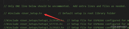
// #define SUPPORT_TRANSACTIONS注释原本的设置文件,并将自定义设置文件取消注释使之生效:
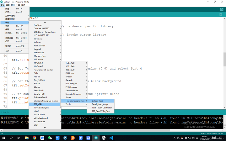
然后烧录例程程序即可,打开如下例程:
然后添加一句屏幕旋转的代码:
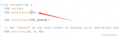
效果如下图:

自定义代码:
/*******************************************************
   Baize_ServoDriver_esp32
   功能:测试显示屏
   引脚:MOSI:21   CLK:18   RS:12   RES:13   CS:5   BLK:15
   Designer: Allen
   E-mail:953598974@qq.com
   Date:2022-08-22
*******************************************************/
#include <SPI.h>
#include <TFT_eSPI.h>

TFT_eSPI TFT = TFT_eSPI();

void setup() {
    TFT.init();
    TFT.setRotation(3);
    TFT.fillScreen(TFT_BLACK);
    TFT.initDMA();
}

void loop() {
  TFT.setCursor(10, 10, 4);//前俩参数是位置(横纵坐标),第三个参数是字体大小
  TFT.setTextColor(TFT_WHITE, TFT_BLACK);
  TFT.println("Hello Allen!\n");
}
效果:

/*******************************************************
   Baize_ServoDriver_esp32
   功能:测试显示屏
   引脚:MOSI:21   CLK:18   RS:12   RES:13   CS:5   BLK:15
   Designer: Allen
   E-mail:953598974@qq.com
   Date:2022-08-22
*******************************************************/
#include <SPI.h>
#include <TFT_eSPI.h>

TFT_eSPI TFT = TFT_eSPI();

void setup() {
    TFT.init();
    TFT.setRotation(3);
    TFT.fillScreen(TFT_BLACK);
    TFT.initDMA();
}

void loop() {
  for(int i=0;i<100;i++)
  {
    TFT.setCursor(10, 10, 4);//前俩参数是位置(横纵坐标),第三个参数是字体大小
    TFT.setTextColor(TFT_WHITE, TFT_BLACK);
    TFT.println("Voltage:\n");
    TFT.setCursor(105, 10, 4);//前俩参数是位置(横纵坐标),第三个参数是字体大小
    TFT.setTextColor(TFT_WHITE, TFT_BLACK);
    TFT.println(i);
    delay(1000);
  }

}
例程10:显示屏电压监测
/*******************************************************
   Baize_ServoDriver_esp32
   功能:测试显示屏
   引脚:MOSI:21   CLK:18   RS:12   RES:13   CS:5   BLK:15
   Designer: Allen
   E-mail:953598974@qq.com
   Date:2022-08-22
*******************************************************/

#include <Wire.h>
#include <Adafruit_PWMServoDriver.h>
#include <SPI.h>
#include <TFT_eSPI.h>

TFT_eSPI TFT = TFT_eSPI();

Adafruit_PWMServoDriver pwm = Adafruit_PWMServoDriver();
Adafruit_PWMServoDriver pwm1 = Adafruit_PWMServoDriver(0x41);

#define SERVOMIN  102               //0.5/20 * 4096 = 102
#define SERVOMID  307               //(102+512)/2=307
#define SERVOMAX  512               //2.5/20 * 4096 = 512
//pcb板测试时,如果是2S的锂电池供电,则以此电压为阈值,低于此电压时,不再驱动舵机运动,保护电池。
int voltage_testpin = 16;
float vol = 0.0;

void setup() {
  TFT.init();
  TFT.setRotation(3);
  TFT.fillScreen(TFT_BLACK);
  TFT.initDMA();

  Serial.begin(115200);
  Serial.println();
  Serial.println("16 channel Servo test!");

  pwm.begin();
  pwm1.begin();
  pwm.setPWMFreq(50);  // Analog servos run at ~50 Hz updates
  pwm1.setPWMFreq(50);  // Analog servos run at ~50 Hz updates

  delay(200);
  for(int i=0;i<16;i++)
  {
    pwm.setPWM(i, 0, SERVOMIN); // 驱动32路舵机转到0度
    pwm1.setPWM(i, 0, SERVOMIN);// 驱动32路舵机转到0度
  }
  delay(2000);
  for (uint16_t pulselen = SERVOMIN; pulselen < SERVOMAX; pulselen++) {
        for(int i=0;i<16;i++)
        {
          pwm.setPWM(i, 0, pulselen);
          pwm1.setPWM(i, 0, pulselen);
        }
        delayMicroseconds(200);
  }
}

void loop() {
     //全部舵机转到0度
        for(int i=0;i<16;i++)
        {
          pwm.setPWM(i, 0, SERVOMIN);
          pwm1.setPWM(i, 0, SERVOMIN);
        }
        delayMicroseconds(200);
        vol = float(analogRead(voltage_testpin))/4095.0*3.3*4.0;
        TFT.setCursor(10, 10, 4);//前俩参数是位置(横纵坐标),第三个参数是字体大小
        TFT.setTextColor(TFT_WHITE, TFT_BLACK);
        TFT.println("Voltage:\n");
        TFT.setCursor(105, 10, 4);//前俩参数是位置(横纵坐标),第三个参数是字体大小
        TFT.setTextColor(TFT_WHITE, TFT_BLACK);
        TFT.println(vol);
        delay(1000);

  //全部舵机转到90度
        for(int i=0;i<16;i++)
        {
          pwm.setPWM(i, 0, SERVOMID);
          pwm1.setPWM(i, 0, SERVOMID);
        }
        delayMicroseconds(200);
        vol = float(analogRead(voltage_testpin))/4095.0*3.3*4.0;
        TFT.setCursor(10, 10, 4);//前俩参数是位置(横纵坐标),第三个参数是字体大小
        TFT.setTextColor(TFT_WHITE, TFT_BLACK);
        TFT.println("Voltage:\n");
        TFT.setCursor(105, 10, 4);//前俩参数是位置(横纵坐标),第三个参数是字体大小
        TFT.setTextColor(TFT_WHITE, TFT_BLACK);
        TFT.println(vol);
        delay(1000);

  //全部舵机转到180度
        for(int i=0;i<16;i++)
        {
          pwm.setPWM(i, 0, SERVOMAX);
          pwm1.setPWM(i, 0, SERVOMAX);
        }
        delayMicroseconds(200);
        vol = float(analogRead(voltage_testpin))/4095.0*3.3*4.0;
        TFT.setCursor(10, 10, 4);//前俩参数是位置(横纵坐标),第三个参数是字体大小
        TFT.setTextColor(TFT_WHITE, TFT_BLACK);
        TFT.println("Voltage:\n");
        TFT.setCursor(105, 10, 4);//前俩参数是位置(横纵坐标),第三个参数是字体大小
        TFT.setTextColor(TFT_WHITE, TFT_BLACK);
        TFT.println(vol);
        delay(1000);

  //全部舵机转到90度
        for(int i=0;i<16;i++)
        {
          pwm.setPWM(i, 0, SERVOMID);
          pwm1.setPWM(i, 0, SERVOMID);
        }
        delayMicroseconds(200);
        vol = float(analogRead(voltage_testpin))/4095.0*3.3*4.0;
        TFT.setCursor(10, 10, 4);//前俩参数是位置(横纵坐标),第三个参数是字体大小
        TFT.setTextColor(TFT_WHITE, TFT_BLACK);
        TFT.println("Voltage:\n");
        TFT.setCursor(105, 10, 4);//前俩参数是位置(横纵坐标),第三个参数是字体大小
        TFT.setTextColor(TFT_WHITE, TFT_BLACK);
        TFT.println(vol);
        delay(1000);

}
例程11:角度映射
/*******************************************************
   Baize_ServoDriver_esp32
   功能:角度映射
   引脚:SDA:21   SCL:22
   对于ARDUINO UNO,SCL:A5,SDA:A4
   Designer: Allen
   E-mail:953598974@qq.com
   Date:2022-08-24
*******************************************************/

//#define SERVOMIN  102               //0.5/20 * 4096 = 102
//#define SERVOMID  307               //1.5/20 * 4096 = 307
//#define SERVOMAX  512               //2.5/20 * 4096 = 512
//实际测试
#define SERVOMIN  102
#define SERVOMID  327
#define SERVOMAX  552


int hello[18]={1500,1529,1500,1549,1529,1481,1434,1500,1355,1466,1513,1546,1423,1452,1500,1444,1529,1586};

void setup() {
  // put your setup code here, to run once:
  Serial.begin(115200);
  Serial.print("{");
  delay(1);
  for(int i=0;i<18;i++)
  {
    Serial.print(map(hello[i],500,2500,SERVOMIN,SERVOMAX));
    Serial.print(",");
    delay(1);
  }
  Serial.print("}");


}

void loop() {
  // put your main code here, to run repeatedly:

}
例程12:串口控制舵机角度
/*******************************************************
   Baize_ServoDriver_esp32
   功能:串口输入角度,板子驱动舵机转到该角度
   引脚:SDA:21   SCL:22
   Designer: Allen
   E-mail:953598974@qq.com
   Date:2022-08-23
 *******************************************************/
#include <Wire.h>
#include <Adafruit_PWMServoDriver.h>

Adafruit_PWMServoDriver pwm = Adafruit_PWMServoDriver();               //驱动1~16或(0~15)号舵机
Adafruit_PWMServoDriver pwm1 = Adafruit_PWMServoDriver(0x41);          //驱动17~32或(16~31)号舵机

#define SERVOMIN  102               //0.5/20 * 4096 = 102
#define SERVOMID  307               //1.5/20 * 4096 = 307
#define SERVOMAX  512               //2.5/20 * 4096 = 512

void setup() {
  // put your setup code here, to run once:
  Serial.begin(115200);

  pwm.begin();
  pwm1.begin();
  pwm.setPWMFreq(50);  // Analog servos run at ~50 Hz updates
  pwm1.setPWMFreq(50);  // Analog servos run at ~50 Hz updates

}

void loop() {
  // put your main code here, to run repeatedly:
  while(!(Serial.available()>0));
  int pwm=Serial.parseInt();

  for(int i=0;i<16;i++)
  {
    pwm.setPWM(i, 0, pwm);
  }
  pwm1.setPWM(0, 0, pwm);
  pwm1.setPWM(1, 0, pwm);
  delay(500);

}
例程13:从显示屏上显示欧拉角
/*******************************************************
   Baize_ServoDriver_esp32
   功能:屏幕显示欧拉角
   引脚:MOSI:21   CLK:18   RS:12   RES:13   CS:5   BLK:15
   Designer: Allen
   E-mail:953598974@qq.com
   Date:2022-09-09 23:03
*******************************************************/
#include <SPI.h>
#include <TFT_eSPI.h>

TFT_eSPI TFT = TFT_eSPI();

#include "I2Cdev.h"

#include "MPU6050_6Axis_MotionApps20.h"

#if I2CDEV_IMPLEMENTATION == I2CDEV_ARDUINO_WIRE
    #include "Wire.h"
#endif

MPU6050 mpu;

#define OUTPUT_READABLE_YAWPITCHROLL

#define INTERRUPT_PIN 2  // use pin 2 on Arduino Uno & most boards
bool blinkState = false;

bool dmpReady = false;  // set true if DMP init was successful
uint8_t mpuIntStatus;   // holds actual interrupt status byte from MPU
uint8_t devStatus;      // return status after each device operation (0 = success, !0 = error)
uint16_t packetSize;    // expected DMP packet size (default is 42 bytes)
uint16_t fifoCount;     // count of all bytes currently in FIFO
uint8_t fifoBuffer[64]; // FIFO storage buffer

// orientation/motion vars
Quaternion q;           // [w, x, y, z]         quaternion container
VectorInt16 aa;         // [x, y, z]            accel sensor measurements
VectorInt16 aaReal;     // [x, y, z]            gravity-free accel sensor measurements
VectorInt16 aaWorld;    // [x, y, z]            world-frame accel sensor measurements
VectorFloat gravity;    // [x, y, z]            gravity vector
float euler[3];         // [psi, theta, phi]    Euler angle container
float ypr[3];           // [yaw, pitch, roll]   yaw/pitch/roll container and gravity vector

// packet structure for InvenSense teapot demo
uint8_t teapotPacket[14] = { '$', 0x02, 0,0, 0,0, 0,0, 0,0, 0x00, 0x00, '\r', '\n' };

volatile bool mpuInterrupt = false;     // indicates whether MPU interrupt pin has gone high
void dmpDataReady() {
    mpuInterrupt = true;
}

void setup() {
    TFT.init();
    TFT.setRotation(3);
    TFT.fillScreen(TFT_BLACK);
    TFT.initDMA();
    // join I2C bus (I2Cdev library doesn't do this automatically)
    #if I2CDEV_IMPLEMENTATION == I2CDEV_ARDUINO_WIRE
        Wire.begin();
        Wire.setClock(400000); // 400kHz I2C clock. Comment this line if having compilation difficulties
    #elif I2CDEV_IMPLEMENTATION == I2CDEV_BUILTIN_FASTWIRE
        Fastwire::setup(400, true);
    #endif
    // initialize serial communication
    // (115200 chosen because it is required for Teapot Demo output, but it's
    // really up to you depending on your project)
    Serial.begin(115200);
    while (!Serial); // wait for Leonardo enumeration, others continue immediately

    // initialize device
    Serial.println(F("Initializing I2C devices..."));
    mpu.initialize();
    pinMode(INTERRUPT_PIN, INPUT);

    // verify connection
    Serial.println(F("Testing device connections..."));
    Serial.println(mpu.testConnection() ? F("MPU6050 connection successful") : F("MPU6050 connection failed"));

    // wait for ready
    Serial.println(F("\nSend any character to begin DMP programming and demo: "));
    while (Serial.available() && Serial.read()); // empty buffer
    while (!Serial.available());                 // wait for data
    while (Serial.available() && Serial.read()); // empty buffer again

    // load and configure the DMP
    Serial.println(F("Initializing DMP..."));
    devStatus = mpu.dmpInitialize();

    // supply your own gyro offsets here, scaled for min sensitivity
    mpu.setXGyroOffset(220);
    mpu.setYGyroOffset(76);
    mpu.setZGyroOffset(-85);
    mpu.setZAccelOffset(1788); // 1688 factory default for my test chip

    // make sure it worked (returns 0 if so)
    if (devStatus == 0) {
        // Calibration Time: generate offsets and calibrate our MPU6050
        mpu.CalibrateAccel(6);
        mpu.CalibrateGyro(6);
        mpu.PrintActiveOffsets();
        // turn on the DMP, now that it's ready
        Serial.println(F("Enabling DMP..."));
        mpu.setDMPEnabled(true);
        // enable Arduino interrupt detection
        Serial.print(F("Enabling interrupt detection (Arduino external interrupt "));
        Serial.print(digitalPinToInterrupt(INTERRUPT_PIN));
        Serial.println(F(")..."));
        attachInterrupt(digitalPinToInterrupt(INTERRUPT_PIN), dmpDataReady, RISING);
        mpuIntStatus = mpu.getIntStatus();
        // set our DMP Ready flag so the main loop() function knows it's okay to use it
        Serial.println(F("DMP ready! Waiting for first interrupt..."));
        dmpReady = true;

        // get expected DMP packet size for later comparison
        packetSize = mpu.dmpGetFIFOPacketSize();
    } else {
        // ERROR!
        // 1 = initial memory load failed
        // 2 = DMP configuration updates failed
        // (if it's going to break, usually the code will be 1)
        Serial.print(F("DMP Initialization failed (code "));
        Serial.print(devStatus);
        Serial.println(F(")"));
    }
}
void loop() {

            TFT.setCursor(10, 10, 4);//前俩参数是位置(横纵坐标),第三个参数是字体大小
            TFT.setTextColor(TFT_WHITE, TFT_BLACK);
            TFT.println("R:");
            TFT.setCursor(50, 10, 4);
            TFT.println(ypr[0] * 180/M_PI);
            TFT.setCursor(10, 40, 4);//前俩参数是位置(横纵坐标),第三个参数是字体大小
            TFT.setTextColor(TFT_WHITE, TFT_BLACK);
            TFT.println("P:");
            TFT.setCursor(50, 40, 4);
            TFT.println(ypr[1] * 180/M_PI);
            TFT.setCursor(10, 70, 4);//前俩参数是位置(横纵坐标),第三个参数是字体大小
            TFT.setTextColor(TFT_WHITE, TFT_BLACK);
            TFT.println("Y:");
            TFT.drawFloat(ypr[2] * 180/M_PI, 3, 50, 70);               // Draw float using current font
//            TFT.setCursor(50, 70, 4);
//            TFT.println(ypr[2] * 180/M_PI);


    // if programming failed, don't try to do anything
    if (!dmpReady) return;
    if (mpu.dmpGetCurrentFIFOPacket(fifoBuffer)) { // Get the Latest packet
            mpu.dmpGetQuaternion(&q, fifoBuffer);
            mpu.dmpGetGravity(&gravity, &q);
            mpu.dmpGetYawPitchRoll(ypr, &q, &gravity);
            Serial.print("ypr\t");
            Serial.print(ypr[0] * 180/M_PI);
            Serial.print("\t");
            Serial.print(ypr[1] * 180/M_PI);
            Serial.print("\t");
            Serial.println(ypr[2] * 180/M_PI);
    }
    delay(50);
    TFT.fillScreen(TFT_BLACK);
}
例程14:按键参数调节
/*******************************************************
   Baize_ServoDriver_esp32
   功能:按键调参
   引脚:MOSI:21   CLK:18   RS:12   RES:13   CS:5   BLK:15
   Designer: Allen
   E-mail:953598974@qq.com
   Date:2022-09-09 23:30
*******************************************************/
#include <SPI.h>
#include <TFT_eSPI.h>
#define key1 35
#define key2 34
#define key3 39
#define key4 36

bool key1s=0,key2s=0,key3s=0,key4s=0;
int a=0,b=0;

TFT_eSPI TFT = TFT_eSPI();
char cmd = 'e';//a:forward b:backward c:left d:right e:stop

long times=0;

void setup() {
  Serial.begin(115200);
    TFT.init();
    TFT.setRotation(3);
    TFT.fillScreen(TFT_BLACK);
    TFT.initDMA();

    pinMode(key1,INPUT);
    pinMode(key2,INPUT);
    pinMode(key3,INPUT);
    pinMode(key4,INPUT);

    times = millis();
}

void loop() {
//  TFT.setCursor(10, 10, 4);//前俩参数是位置(横纵坐标),第三个参数是字体大小
//  TFT.setTextColor(TFT_WHITE, TFT_BLACK);
//  TFT.println("Hello Allen!\n");
  if(cmd == 'a')
  {

  }
  else if(cmd == 'b')
  {

  }
  else if(cmd == 'd')
  {

  }
  else if(cmd =='e')
  {
    Serial.println("hello");
    if(digitalRead(key1)==1)
    {
      delay(5);
      if(digitalRead(key1)==1)
      {
        if(key1s==0)
        {
          a++;
          key1s=1;

        }
      }
    }
    if(digitalRead(key1)==0)
    {
      delay(5);
      if(digitalRead(key1)==0)
      {
        if(key1s==1)
        {
          key1s=0;

        }
      }
    }
    if(digitalRead(key2)==1)
    {
      delay(5);
      if(digitalRead(key2)==1)
      {
        if(key2s==0)
        {
          a--;
          key2s=1;
        }
      }
    }
    if(digitalRead(key2)==0)
    {
      delay(5);
      if(digitalRead(key2)==0)
      {
        if(key2s==1)
        {
          key2s=0;
        }
      }
    }
  }
  else if(cmd == 'f')
  {

  }
          TFT.setCursor(10, 10, 4);//前俩参数是位置(横纵坐标),第三个参数是字体大小
          TFT.setTextColor(TFT_WHITE, TFT_BLACK);
          TFT.println("a:");
          TFT.drawNumber(a, 50, 10);               // Draw float using current font
  if(millis()-times>100)
  {
    TFT.fillScreen(TFT_BLACK);
    times = millis();
  }
}
加强版,可以切换参数,多参数调节
/*******************************************************
   Baize_ServoDriver_esp32
   功能:按键调参
   引脚:MOSI:21   CLK:18   RS:12   RES:13   CS:5   BLK:15
   Designer: Allen
   E-mail:953598974@qq.com
   Date:2022-09-10 16:54
*******************************************************/
#include <SPI.h>
#include <TFT_eSPI.h>
#define key1 35
#define key2 34
#define key3 39
#define key4 36

bool key1s=0,key2s=0,key3s=0,key4s=0;
int a=0,b=0;

//光标位置,一共四行,定义为0,1,2,3
int insert_f=0;

struct pr{
  String name;
  int num;
};

pr pro[4]={"P:",0,"I:",0,"D:",0,"O:",0};


TFT_eSPI TFT = TFT_eSPI();
char cmd = 'e';//a:forward b:backward c:left d:right e:stop

long times=0;

void setup() {
  Serial.begin(115200);
    TFT.init();
    TFT.setRotation(3);
    TFT.fillScreen(TFT_BLACK);
    TFT.initDMA();

    pinMode(key1,INPUT);
    pinMode(key2,INPUT);
    pinMode(key3,INPUT);
    pinMode(key4,INPUT);

    times = millis();
}

void loop() {
//  for(int i=0;i<4;i++)
//  {
//          TFT.setCursor(50, 30*(i), 4);//前俩参数是位置(横纵坐标),第三个参数是字体大小
//          TFT.setTextColor(TFT_WHITE, TFT_BLACK);
//          TFT.println("      ");
//  }

  if(millis()-times>100)
  {
    TFT.fillScreen(TFT_BLACK);
    times = millis();
  }

//  TFT.setCursor(10, 10, 4);//前俩参数是位置(横纵坐标),第三个参数是字体大小
//  TFT.setTextColor(TFT_WHITE, TFT_BLACK);
//  TFT.println("Hello Allen!\n");
  if(cmd == 'a')
  {

  }
  else if(cmd == 'b')
  {

  }
  else if(cmd == 'c')
  {

  }
  else if(cmd == 'd')
  {

  }
  else if(cmd =='e')
  {
    Serial.println("hello");
    if(digitalRead(key1)==1)
    {
      delayMicroseconds(10);
      if(digitalRead(key1)==1)
      {
        if(key1s==0)
        {
          pro[insert_f].num++;
          key1s=1;

        }
//        else
//        {
//          pro[insert_f].num++;
//          delay(500);
//        }
      }
    }
    if(digitalRead(key1)==0)
    {
      delayMicroseconds(10);
      if(digitalRead(key1)==0)
      {
        if(key1s==1)
        {
          key1s=0;
        }
      }
    }

    if(digitalRead(key2)==1)
    {
      delayMicroseconds(10);
      if(digitalRead(key2)==1)
      {
        if(key2s==0)
        {
          pro[insert_f].num--;
          key2s=1;
        }
//        else
//        {
//          pro[insert_f].num--;
//          delay(500);
//        }
      }
    }
    if(digitalRead(key2)==0)
    {
      delayMicroseconds(10);
      if(digitalRead(key2)==0)
      {
        if(key2s==1)
        {
          key2s=0;
        }
      }
    }
    //key3:向上翻页
    if(digitalRead(key3)==1)
    {
      delayMicroseconds(10);
      if(digitalRead(key3)==1)
      {
        if(key3s==0)
        {
          if(insert_f==0)
          {
            insert_f=3;
          }
          else
            insert_f--;

          key3s=1;
        }
      }
    }
    if(digitalRead(key3)==0)
    {
      delayMicroseconds(10);
      if(digitalRead(key3)==0)
      {
        if(key3s==1)
        {
          key3s=0;
        }
      }
    }
    //key4:向下翻页
    if(digitalRead(key4)==1)
    {
      delayMicroseconds(10);
      if(digitalRead(key4)==1)
      {
        if(key4s==0)
        {
          if(insert_f==3)
          {
            insert_f=0;
          }
          else
            insert_f++;

          key4s=1;
        }
      }
    }
    if(digitalRead(key4)==0)
    {
      delayMicroseconds(10);
      if(digitalRead(key4)==0)
      {
        if(key4s==1)
        {
          key4s=0;
        }
      }
    }

  }
  else if(cmd == 'f')
  {

  }
  for(int i=0;i<4;i++)
  {
          TFT.setCursor(10, 30*(i), 4);//前俩参数是位置(横纵坐标),第三个参数是字体大小
          TFT.setTextColor(TFT_WHITE, TFT_BLACK);
          TFT.println(pro[i].name);
          TFT.drawNumber(pro[i].num, 50, 30*(i));               // Draw float using current font
  }
          TFT.setCursor(120, 30*(insert_f), 4);//前俩参数是位置(横纵坐标),第三个参数是字体大小
          TFT.setTextColor(TFT_WHITE, TFT_BLACK);
          TFT.println("<--");


}
例程15:连接wifi热点
/*******************************************************
   Baize_ServoDriver_esp32
   功能:连接WiFi热点
   引脚:key1:35    key2:34    key3:39    key4:36
   Designer: Allen
   E-mail:953598974@qq.com
   Date:2022-09-13 15:06
*******************************************************/
#include <WiFi.h>
#define MAX_SRV_CLIENTS 3   //最大同时联接数,即你想要接入的设备数量,8266tcpserver只能接入五个,哎

const char *ssid = "Baize";
const char *password = "baizerobot";

WiFiServer server(8266);//你要的端口号,随意修改,范围0-65535
WiFiClient serverClients[MAX_SRV_CLIENTS];

void setup()
{
    Serial.begin(9600);
    delay(10);
    pinMode(16, OUTPUT);
    digitalWrite(16, 0);
    WiFi.begin(ssid, password);

    while (WiFi.status() != WL_CONNECTED)
    {
        delay(500);
    }
    server.begin();
    server.setNoDelay(true);  //加上后才正常些
}

void loop()
{
    blink();

    uint8_t i;
    if (server.hasClient())
    {
        for (i = 0; i < MAX_SRV_CLIENTS; i++)
        {
            if (!serverClients[i] || !serverClients[i].connected())
            {
                if (serverClients[i]) serverClients[i].stop();//未联接,就释放
                serverClients[i] = server.available();//分配新的
                continue;
            }

        }
        WiFiClient serverClient = server.available();
        serverClient.stop();
    }
    for (i = 0; i < MAX_SRV_CLIENTS; i++)
    {
        if (serverClients[i] && serverClients[i].connected())
        {
            digitalWrite(16, 0);//有链接存在,就一直长亮

            if (serverClients[i].available())
            {
                while (serverClients[i].available())
                    Serial.write(serverClients[i].read());
            }
        }
    }
    if (Serial.available())
    {
        size_t len = Serial.available();
        uint8_t sbuf[len];
        Serial.readBytes(sbuf, len);
        //push UART data to all connected telnet clients
        for (i = 0; i < MAX_SRV_CLIENTS; i++)
        {
            if (serverClients[i] && serverClients[i].connected())
            {
                serverClients[i].write(sbuf, len);  //向所有客户端发送数据
                delay(1);
            }
        }
    }
}


void blink()
{
    static long previousMillis = 0;
    static int currstate = 0;

    if (millis() - previousMillis > 200)  //200ms
    {
        previousMillis = millis();
        currstate = 1 - currstate;
        digitalWrite(16, currstate);
    }
}
例程16:ESP32-ROS串口话题通信(发布话题)
/*
 * rosserial Publisher Example
 * Prints "hello world!"
 */
/*******************************************************
   Baize_ServoDriver_esp32
   功能:WiFi话题通信
   引脚:SDA:21   SCL:22
   Designer: Allen
   E-mail:953598974@qq.com
   Date:2022-09-13 19:35
 *******************************************************/


#include <ros.h>
#include <std_msgs/String.h>
#include <SPI.h>
#include <TFT_eSPI.h>       // Hardware-specific library
TFT_eSPI TFT = TFT_eSPI();  // Invoke custom library

ros::NodeHandle  nh;
std_msgs::String str_msg;
ros::Publisher chatter("chatter", &str_msg);
char hello[15] = "hello world!";
long time_s=0;
void setup()
{
  nh.initNode();
  nh.advertise(chatter);
    TFT.init();
    TFT.setRotation(3);
    TFT.fillScreen(TFT_BLACK);
    TFT.initDMA();
  TFT.setCursor(0, 0, 4);
  // Set the font colour to be white with a black background
  TFT.setTextColor(TFT_WHITE, TFT_BLACK);
  // We can now plot text on screen using the "print" class
  TFT.println("Initialised default\n");
  time_s = millis();
}
void loop()
{
    str_msg.data = hello;
    chatter.publish( &str_msg );
    nh.spinOnce();
    time_s = millis();
  delay(1000);
}
例程17:ESP32-ROS串口话题通信(订阅话题消息并在显示屏上显示)
/*******************************************************
   Baize_ServoDriver_esp32
   功能:WiFi话题通信订阅消息并显示
   引脚:SDA:21   SCL:22
   Designer: Allen
   E-mail:953598974@qq.com
   Date:2022-09-13 21:40
 *******************************************************/
#include <ros.h>
#include <std_msgs/String.h>

#include <SPI.h>
#include <TFT_eSPI.h>       // Hardware-specific library
TFT_eSPI TFT = TFT_eSPI();  // Invoke custom library


void chatterCallback(const std_msgs::String& msg) {
//  TFT.fillScreen(TFT_BLACK);
  TFT.setCursor(0, 30, 4);
  // Set the font colour to be white with a black background
  TFT.setTextColor(TFT_WHITE, TFT_BLACK);

  // We can now plot text on screen using the "print" class
  TFT.println(msg.data);
}

ros::NodeHandle  nh;

std_msgs::String str_msg;
ros::Publisher chatter("gun", &str_msg);
ros::Subscriber<std_msgs::String> sub("message", chatterCallback);
char hello[13] = "hello!";


void setup()
{
  nh.initNode();
  nh.advertise(chatter);
  nh.subscribe(sub);

    TFT.init();
    TFT.setRotation(3);
    TFT.fillScreen(TFT_BLACK);
    TFT.initDMA();

  TFT.setCursor(0, 0, 4);
  // Set the font colour to be white with a black background
  TFT.setTextColor(TFT_WHITE, TFT_BLACK);

  // We can now plot text on screen using the "print" class
  TFT.println("Initialised default\n");
}

void loop()
{
    str_msg.data = hello;
    chatter.publish( &str_msg );

    nh.spinOnce();

  delay(1000);
}
例程18:获取网络时间并显示在显示屏上
/**
  ESP32 最简单直接获取网络时间方法
*/

#include <WiFi.h>
#include <SPI.h>
#include <TFT_eSPI.h>

TFT_eSPI TFT = TFT_eSPI();


#define NTP1  "ntp1.aliyun.com"
#define NTP2  "ntp2.aliyun.com"
#define NTP3  "ntp3.aliyun.com"

//填写WIFI入网信息
const char* ssid     = "Zhitong";     // WIFI账户
const char* password = "95359897"; // WIFI密码

void setClock() {
  struct tm timeinfo;
    if (!getLocalTime(&timeinfo))
    {//如果获取失败,就开启联网模式,获取时间
        Serial.println("Failed to obtain time");
     //    WiFi.disconnect(false);
        WiFi.mode(WIFI_STA);//开启网络
       WiFi.begin(ssid, password);
         while (WiFi.status() != WL_CONNECTED)
    {
        delay(500);
        Serial.print(".");
    }
     configTime(8 * 3600, 0, NTP1, NTP2,NTP3);
        return;
    }
    Serial.println(&timeinfo, "%F %T %A"); // 格式化输出:2021-10-24 23:00:44 Sunday
    Serial.print(asctime(&timeinfo));//默认打印格式:Mon Oct 25 11:13:29 2021
  //   WiFi.disconnect(true);//断开网络连接,关闭网络
  TFT.fillScreen(TFT_BLACK);
  TFT.setCursor(0, 0, 4);//前俩参数是位置(横纵坐标),第三个参数是字体大小
  TFT.setTextColor(TFT_WHITE, TFT_BLACK);
  TFT.println(asctime(&timeinfo));
}

void setup()
{
  TFT.init();
    TFT.setRotation(3);
    TFT.fillScreen(TFT_BLACK);
    TFT.initDMA();

    Serial.begin(115200);
    Serial.println();
 //设置ESP32工作模式为无线终端模式
  WiFi.mode(WIFI_STA);
  WiFi.begin(ssid, password);
    while (WiFi.status() != WL_CONNECTED)
    {
        delay(500);
        Serial.print(".");
    }
    Serial.println("WiFi connected!");
 configTime(8 * 3600, 0, NTP1, NTP2,NTP3);
      setClock();
    // 从网络时间服务器上获取并设置时间
    // 获取成功后芯片会使用RTC时钟保持时间的更新

//    WiFi.disconnect(true);//断开wifi网络
//    WiFi.mode(WIFI_OFF);//关闭网络
    Serial.println("WiFi disconnected!");
}

void loop()
{
  Serial.println("Waiting 10s before the next round...");
  delay(1000);
  setClock();
}
问题汇总
1.焊接完成以后,esp32模组发烫
板子焊接完成之后,在测试过程中,发现esp32模组一直在发烫,找不到原因,用万用表测量之后发现3V3和GND短路了。但是不知道在整个电路中到底是哪个部分短路的,因为板子上有大量的3V3和GND。
然后考虑到,可以先把esp32模组取下来,然后再测试,由于取下来再焊上去非常麻烦。所以就用割板刀把esp32模组的3V3电源供电给断开,这样esp32模组就从3V3供电里面隔离出来了,然后再次用万用表测量之后,发现除了esp32模组之外,另一边的3V3和GND是正常的。而esp32模组这边的3V3和GND是短路的,这边只有esp32模组这一个元器件,所以推测是esp32模组短路,看来还是要拆下来esp32模组。
最终将esp32模组拆下来换了一个新的上去,发现一切正常。单独测量那个换下来的esp32模组,发现他本身还是短路的。
最终虽然解决了问题,但是由于模组都是新的,也不知道第一个模组是为什么短路了。
焊接是用的焊台焊接的,不知道是不是焊接过程中,esp32模组内部的元器件是否发生了错位,最后导致的模组内部短路。


评论(0)
您还未登录,请登录后发表或查看评论